


OUTPUT RECTIFIER BRIDGE REMOVAL AND REPLACEMENT (continued)
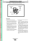
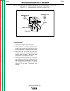
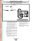
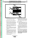
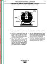
FIGURE F.20 - OUTPUT RECTIFIER CONNECTIONS
203
W2
W1
204
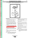
PROCEDURE
1. Remove the engine spark plug wire to pre-
vent accidental kickback or starting.
2. With the 5/16" nut driver, remove the 8
sheet metal screws from the case top.
3. With the 7/16" wrench, remove the heavy
leads W1 and W2 from the stud terminals.
You do not have to remove the diode pig-
tails from the terminals. See Figure F.20.
4. With the 7/16" wrench, remove the "N"
negative lead and the #204 lead from the
negative heat sink. Note placement of the
leads for reassembly.
5. With the 7/16" wrench, remove the choke
lead and the #203 lead from the positive
heat sink. Note placement of the leads for
reassembly.
6. With the 3/8" wrench, remove the four
mounting screws holding the output rectifi-
er bridge assembly to the choke. Note the
placement of the insulators. When you
reassemble the output rectifier bridge, the
heat sink assembly MUST be electrically
isolated from case ground.
7. Carefully lift up and remove the output rec-
tifier bridge assembly.
8. Reassembly: Refer to the Wiring Diagram
for proper connections to the positive and
negative sides of the rectifier assembly.
The two sides of the bridge are marked +
and –, respectively.
NOTE: Use Dow Corning 340 on all aluminum
electrical connection surfaces. If you
replace individual diodes, use Dow
Corning 340 on all mating surfaces
between the diodes and the heatsink.
9. Install the rectifier bridge assembly by tilt-
ing it down into its position above the
choke assembly. Be sure that the positive
(+) side of the bridge, as marked, is on the
right side of the machine, looking from the
case front.
10. With the 3/8" wrench and slot head screw
driver, install the four mounting screws
(two on each side). Note the placement of
the nylon insulators. These must be in
place when you install the rectifier
bridge assembly in order to electrically
insulate the bridge from the choke lam-
ination assembly.
TROUBLESHOOTING & REPAIR
F-48 F-48
WELDANPOWER 125
Return to Section TOC Return to Section TOC Return to Section TOC Return to Section TOC
Return to Master TOC Return to Master TOC Return to Master TOC Return to Master TOC