


Return to Section TOC Return to Section TOC Return to Section TOC Return to Section TOC
Return to Master TOC Return to Master TOC Return to Master TOC Return to Master TOC
OPERATION
E-4 E-4
WELDANPOWER 125
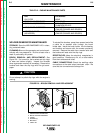
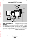
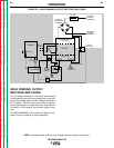
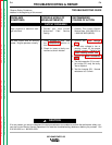
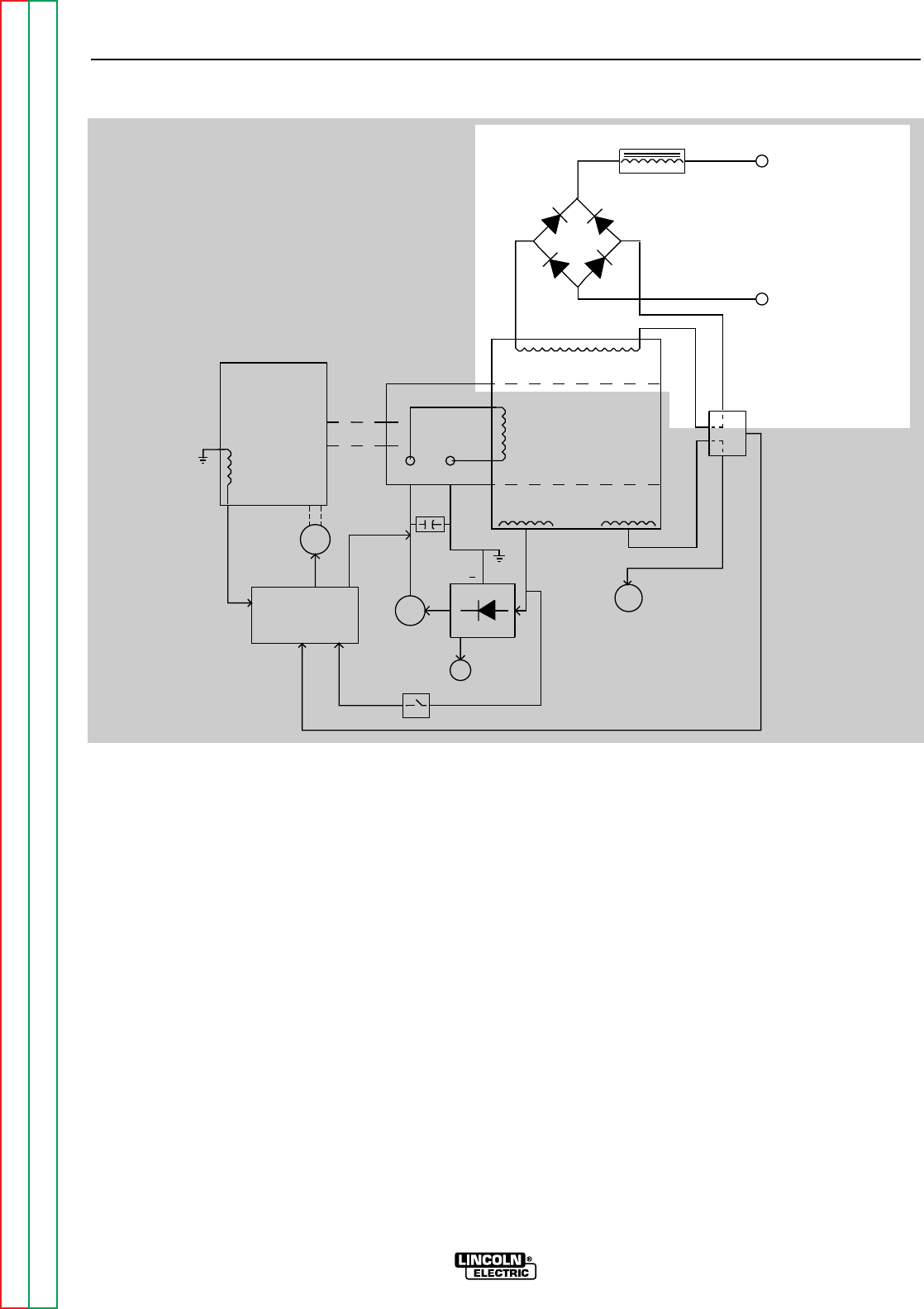
FIGURE E.4 – WELD WINDING, OUTPUT RECTIFIER AND CHOKE
NOTE: Unshaded areas of Block Logic Diagram are the subject of discussion.
WELD WINDING, OUTPUT
RECTIFIER AND CHOKE
The AC voltage developed in the stator weld winding
is delivered through the current transformer to the out-
put rectifier bridge, where the AC voltage is rectified to
a DC voltage. The DC current path from the output of
the rectifier bridge is through the choke, where the DC
is filtered, to the negative and positive output termi-
nals.
The WELDANPOWER 125 provides 125 amps of con-
stant current DC welding for stick electrodes.
ENGINE
MECHANICAL
ROTATION
STATOR
ROTOR
STATOR
CHOKE
ROTOR
SLIP
RINGS
CAPACITORS
IDLER
SOLENOID
IDLER
P.C. BOARD
IDLE
SWITCH
RHEOSTAT
HOUR
METER
115 AND 230 VAC
RECEPTACLES
FIELD
RECTIFIER
BRIDGE
MAGNETO
OUTPUT
RECTIFIER
BRIDGE
POSITIVE
OUTPUT
TERMINAL
NEGATIVE
OUTPUT
TERMINAL
+
CURRENT
TRANSFORMER