


RHEOSTAT REMOVAL AND REPLACEMENT (continued)
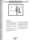
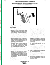
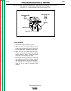
FIGURE F.15 - RHEOSTAT REMOVAL
PROCEDURE
1. Remove the spark plug wire.
2. With the 5/16” nut driver, remove the 8
sheet metal screws that hold the top cover
to the control box. Remove the top cover.
3. With the 5/16” nut driver and the 5/16”
wrench, remove the 6 screws that hold the
control panel in place. Move the panel
aside as far as the leads will allow.
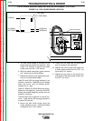
4. With the small slot head screw driver,
loosen the screw that holds the knob to the
rheostat shaft. The shaft has a flat for
locating the knob at reassembly.
5. With a 9/16” open or box end wrench,
remove the nut that holds the rheostat to
the control panel. Support the rheostat
with your hand as you turn the nut. There
is a shake-proof washer under the nut.
6. Pull the rheostat back out of the control
panel and lay it out on its wires to loosen
the nuts that hold them.
7. With the 5/16” open or box end wrench,
remove the brass nuts from the wire termi-
nals. Support the terminals as you turn the
wrench to avoid ripping the terminals from
their foundations. Note the wire locations
for reassembly.
Note: The brass screws are double-nutted
with a shake-proof star washer under the
screw head.
8. To reinstall the rheostat, replace each of
the brass screws. Place a shake-proof
star washer under the head, insert the
screw into the rheostat and tighten down
one nut. Replace the appropriate wires
and tighten down the second nut. Again,
support the terminals as you turn the
wrench to avoid ripping the terminals
from their foundations.
9. Reassemble the rheostat to the front of
the control panel. Line up the locating tab
on the rheostat with the slot on the con-
trol panel hole.
10. Reassemble the shake-proof star washer
and nut and tighten securely with the
9/16” wrench.
11. Locate the flat spot on the shaft, line up
the knob locking screw, push the knob
onto the shaft and tighten the screw with
the small slot head screw driver.
12. Check the rheostat knob for proper rota-
tion, minimum to maximum.
13. Replace the control panel and tighten the
6 sheet metal screws with the 5/16” nut
driver and 5/16” wrench.
14. Replace the top cover of the control box
and tighten the 8 sheet metal screws with
the 5/16” nut driver.
TROUBLESHOOTING & REPAIR
F-39 F-39
WELDANPOWER 125
Return to Section TOC Return to Section TOC Return to Section TOC Return to Section TOC
Return to Master TOC Return to Master TOC Return to Master TOC Return to Master TOC
See Figure F.15 for steps 3 - 9.