


Return to Section TOC Return to Section TOC Return to Section TOC Return to Section TOC
Return to Master TOC Return to Master TOC Return to Master TOC Return to Master TOC
OPERATION
E-3 E-3
WELDANPOWER 125
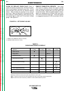
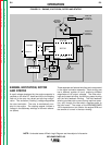
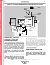
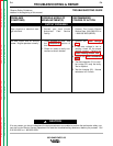
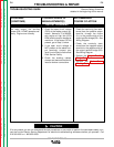
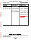
FIGURE E.3 – ROTOR FIELD FEEDBACK, AUXILIARY POWER AND ENGINE IDLE CONTROL
NOTE: Unshaded areas of Block Logic Diagram are the subject of discussion.
ROTOR FIELD FEEDBACK,
AUXILIARY POWER AND
ENGINE IDLE CONTROL
The AC voltage developed in the field winding is fed to
the full wave rectifier bridge. The DC output of the
bridge is filtered by the field capacitor and controlled
by the output rheostat. This filtered and controlled
feedback voltage is fed to the rotor winding via the
brush and slip ring configuration. As the feedback
voltage is increased or decreased, the outputs of the
weld and auxiliary windings are likewise increased or
decreased.
The hour meter is also powered by the field rectifier
bridge. When field voltage is present, the hour meter
will run.
When full field voltage is applied to the rotor and the
engine is running at high speed (3700 RPM), a 230VAC
voltage is developed in the stator auxiliary winding.
This winding is tapped. Each half of this winding pro-
vides 115 VAC to each side of the 115V duplex recep-
tacle. The two voltages (115VAC and 230VAC) are
connected to the appropriate receptacles and offer
4500 watts (total) of AC power.
The idler solenoid is mechanically connected to the
engine throttle linkage. The field winding provides
power for the idler P.C. board and also to the idler
solenoid, which brings the engine to a low idle state.
When output current, either weld or auxiliary, is sensed
by the current transformer, the P.C. board deactivates
the idler solenoid, and the engine returns to high RPM.
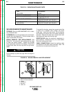
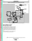
AUXILIARY POWER
OVERCURRENT PROTECTION
The 4500 watt auxiliary power winding and circuitry is
protected from an overload condition by two 20 amp
circuit breakers. The circuit breakers are located
below the output receptacles. They can be manually
reset.
ENGINE
MECHANICAL
ROTATION
STATOR
ROTOR
STATOR
CHOKE
ROTOR
SLIP
RINGS
CAPACITORS
IDLER
SOLENOID
IDLER
P.C. BOARD
IDLE
SWITCH
RHEOSTAT
HOUR
METER
115 AND 230 VAC
RECEPTACLES
FIELD
RECTIFIER
BRIDGE
MAGNETO
OUTPUT
RECTIFIER
BRIDGE
POSITIVE
OUTPUT
TERMINAL
NEGATIVE
OUTPUT
TERMINAL
+
CURRENT
TRANSFORMER