


Section F-1 Section F-1
WELDANPOWER 125
Troubleshooting & Repair Section.................................................................................Section F
How to Use Troubleshooting Guide ......................................................................................F-2
PC Board Troubleshooting Procedures.................................................................................F-3
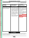
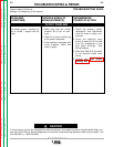
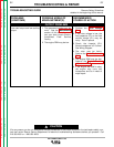
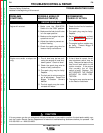
Troubleshooting Guide.................................................................................................F4 - F-12
Test Procedures
Rotor Voltage Test.........................................................................................................F-13
Rotor Resistance Test ...................................................................................................F-15
Output Rectifier Bridge Test..........................................................................................F-18
Main Stator Test ............................................................................................................F-20
Rotor “Flashing” Circuit Test.........................................................................................F-23
Engine Throttle Adjustment Test ...................................................................................F-26
Oscilloscope Waveforms
Normal Open Circuit Weld Voltage Waveform..............................................................F-31
Normal Open Circuit Voltage Waveform (115 VAC Supply)..........................................F-32
Typical Weld Output Waveform - Machine Loaded ......................................................F-33
Abnormal Open Circuit Weld Voltage Waveform ..........................................................F-34
Replacement Procedures
Brush Removal and Replacement ................................................................................F-35
Rheostat Removal and Replacement ..........................................................................F-38
Field Capacitor Removal and Replacement .................................................................F-40
Field Diode Bridge Removal and Replacement............................................................F-42
Idler Printed Circuit Board Removal and Replacement................................................F-45
Output Rectifier Bridge Removal and Replacement.....................................................F-47
Output Choke Removal and Replacement ...................................................................F-50
Stator/Rotor Removal and Replacement (Kit S20925) .................................................F-53
Retest After Repair ..............................................................................................................F-59
TABLE OF CONTENTS
TROUBLE SHOOTING & REPAIR SECTION
Return to Master TOC Return to Master TOC Return to Master TOC Return to Master TOC