


FIELD DIODE BRIDGE REMOVAL AND REPLACEMENT (continued)
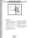
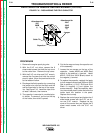
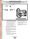
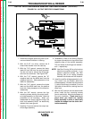
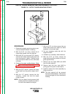
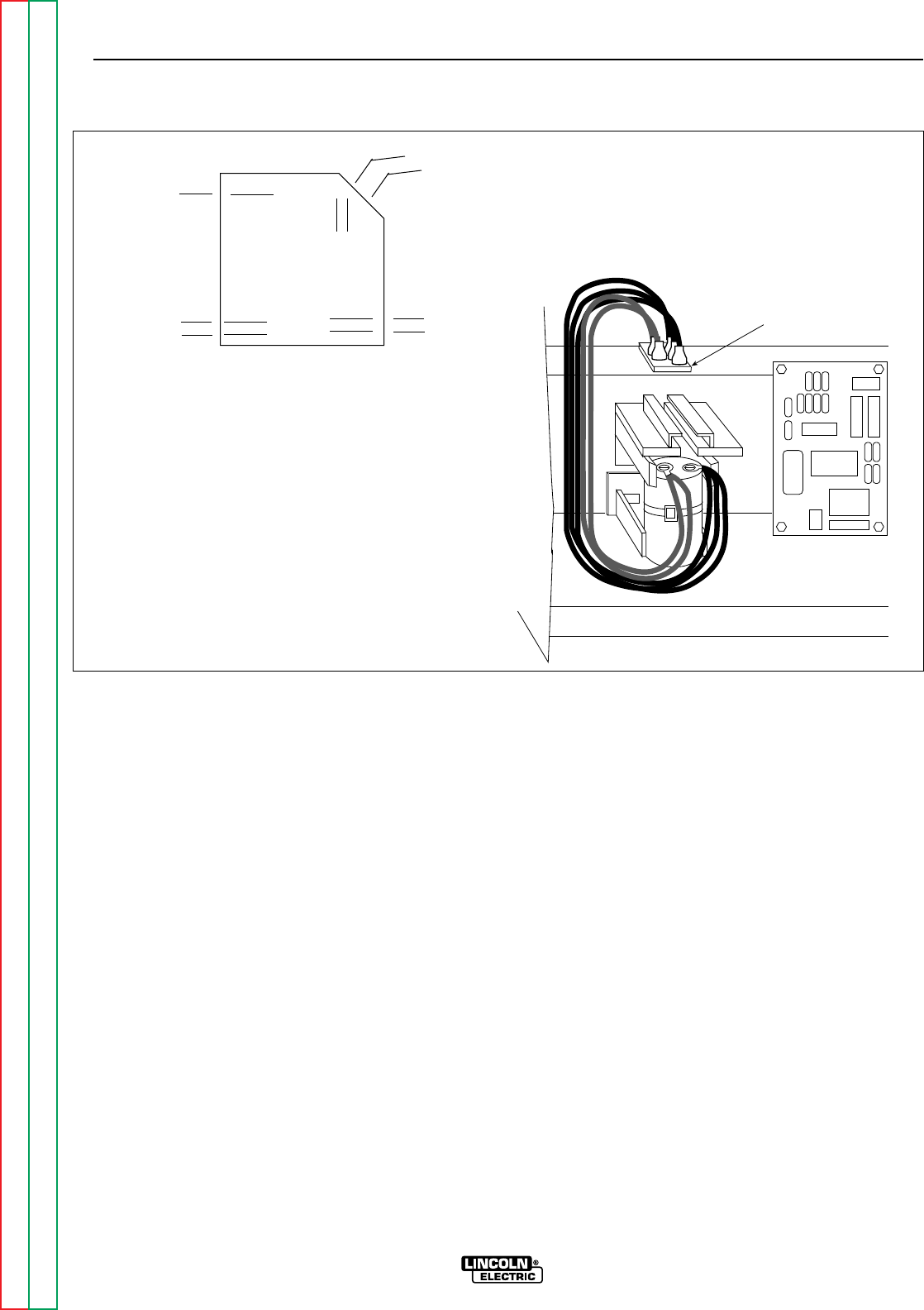
FIGURE F.18 - FIELD DIODE BRIDGE LOCATION
Feild Diode Bridge
5. The field diode bridge is mounted to the
sheet metal just above the capacitor. See
Figure F.18. Remove it using the slot head
screw driver and the 11/32” wrench.
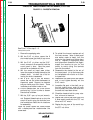
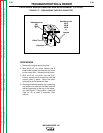
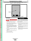
6. With the needle nose pliers, gently remove
the 7 wires from the diode bridge.
7. Replace the wires to their appropriate loca-
tions on the new diode bridge:
Lead 200 and 200C are piggy-backed to the
positive (+) terminal. Depending on the bridge
used, this corner may be beveled and/or
marked with a + sign.
Lead 201 (Black) and 201B (Black) are piggy-
backed on the negative (–) terminal, which will
always be located diagonally across from the
positive (+) terminal.
The Blue lead (7A) is attached to one AC ter-
minal. Leads 9A and 9B are piggy-backed to
the other AC terminal.
8. Mount the field diode bridge using the
screw, washers and nut. Use the slot head
screwdriver and 11/32” wrench.
9. Check that the leads are not grounded
and for clearance and tightness.
10. Replace the control panel and tighten the
6 sheet metal screws with the 5/16” nut
driver and 5/16” wrench.
11. Replace the top cover of the control box
and tighten the 8 sheet metal screws with
the 5/16” nut driver.
TROUBLESHOOTING & REPAIR
F-44 F-44
WELDANPOWER 125
Return to Section TOC Return to Section TOC Return to Section TOC Return to Section TOC
Return to Master TOC Return to Master TOC Return to Master TOC Return to Master TOC
7A (Blue)
Field Diode Bridge
201 (Black)
201C (Black)
9A (Brown)
200 (Red)
200C (Red)
9B (Brown)
+
–