


Return to Section TOC Return to Section TOC Return to Section TOC Return to Section TOC
Return to Master TOC Return to Master TOC Return to Master TOC Return to Master TOC
TROUBLESHOOTING & REPAIR
F-5 F-5
WELDANPOWER 125
TROUBLESHOOTING GUIDE Observe Safety Guidelines
detailed in the beginning of this manual.
CAUTION
If for any reason you do not understand the test procedures or are unable to perform the test/repairs safely, con-
tact the Lincoln Electric Service Department for electrical troubleshooting assistance before you proceed. Call
216-383-2531 or 1-800-833-9353.
PROBLEMS
(SYMPTOMS)
POSSIBLE AREAS OF
MISADJUSTMENT(S)
RECOMMENDED
COURSE OF ACTION
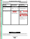
OUTPUT PROBLEMS
No weld output, the auxiliary
power (230-115VAC) operates nor-
mally. Engine runs normally.
1. Check the open circuit voltage
(OCV) at the welder output ter-
minals. Normal is 75 to 82VDC
with engine at high idle (3750
RPM) and the output rheostat at
maximum. If the correct OCV is
present, go to Step 3, below.
2. If the open circuit voltage is
NOT present at the welder out-
put terminals, contact your
local Lincoln Electric Authorized
Field Service Facility.
3. Check the welding cables,
clamps and electrode holder for
loose or broken connections.
1. Check the continuity (low resis-
tance) from the positive output
terminal, through the choke
(L1), to the positive side of the
output rectifier bridge (D2). See
Wiring Diagram.
2. Check the continuity (zero
ohms) from the negative output
terminal to the negative side of
the output rectifier bridge (D2).
See Wiring Diagram.
3. Perform the Output Rectifier
Bridge Test.
4. Perform the Main Stator
Winding Test.