


Return to Section TOC Return to Section TOC Return to Section TOC Return to Section TOC
Return to Master TOC Return to Master TOC Return to Master TOC Return to Master TOC
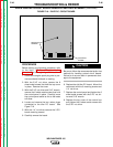
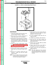
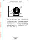
STATOR/ROTOR REMOVAL AND REPLACEMENT(continued)
STATOR REMOVAL PROCEDURE
1. Remove the engine spark plug wire to pre-
vent accidental kickback or starting.
2. Perform the Output Rectifier Bridge
Removal procedure.
3. Perform the Output Choke Removal proce-
dure.
4. Remove lead #14A from the control box
assembly.
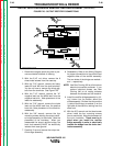
5. With the 5/16" nut driver, remove the 4
sheet metal screws that mount the control
box assembly to the stator frame.
6. Unplug the large 6 pin molex plug (quick
connect).
7. Cut any necessary cable ties.
8. Remove the W1 lead from the current
transformer.
9. Remove the green ground lead (GND-C)
from the wiring harness loom.
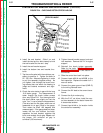
10. With the slot head screw driver, remove
leads #201A and 202B from the field
capacitor. It may be necessary to cut the
cable tie that holds the capacitor into its
mounting bracket.
11. Carefully slide out the control box assem-
bly (with the control panel). Be careful to
clear the leads and the solenoid plunger
and throttle linkage.
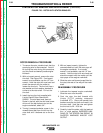
12. Remove the brush holder assembly. Open
the brush holder assembly cover.
Squeeze the 2 tabs and depress the cover
at the top with a screw driver or your fin-
gernail. The cover will drop open on its
bottom hinge. With the 1/4" nut driver,
remove the 2 screws that hold the brush
holder assembly in place. With the needle
nose pliers, gently remove the black and
the red wires. Set the brush holder aside.
Pull the wires up into the control box.
TROUBLESHOOTING & REPAIR
F-54 F-54
WELDANPOWER 125