


ROTOR “FLASHING” CIRCUIT TEST (continued)
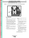
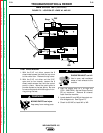
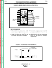
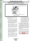
FIGURE F.8 - BRUSH HOLDER LEADS 201A(-) AND 202B (+)
Slip
Rings
201A(-)
202B(+)
TEST PROCEDURE
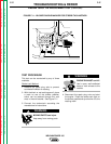
1. With the 5/16" nut driver, remove the 8
sheet metal screws that hold the top cover
to the control box. Remove the top cover.
2. Locate and remove lead #201A from the
brush holder. See Figure F.8 for location.
3. Connect the negative (-) lead of the DC
ammeter to lead #201A and the positive (+)
lead to the brush holder.
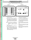
4. Remove lead #7A from field diode bridge
rectifier D1. See Figure F.9. Electrically
isolate the lead.
TROUBLESHOOTING & REPAIR
F-24 F-24
WELDANPOWER 125
Return to Section TOC Return to Section TOC Return to Section TOC Return to Section TOC
Return to Master TOC Return to Master TOC Return to Master TOC Return to Master TOC
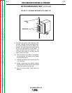
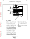
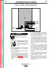
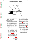
FIGURE F.9 - DIODE BRIDGE LEAD ASSIGNMENTS
7A (Blue)
201 (Black)
201C (Black)
9A (Brown)
200 (Red)
200C (Red)
9B (Brown)
+
–