


MAIN STATOR TEST (continued)
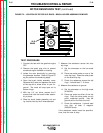
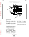
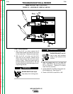
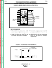
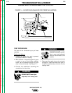
FIGURE F.6 - MAIN STATOR MOLEX PLUG TEST POINTS
FIGURE F.6
MAIN STATOR MOLEX PLUG TEST POINTS
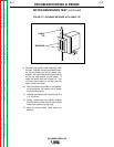
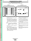
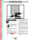
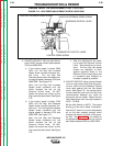
FIGURE F.7
DIODE BRIDGE LEAD ASSIGNMENTS
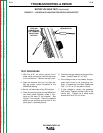
5. Locate the 6 pin molex type connector
from the main stator.
6. Check for 240 - 260 VAC at leads #6A to
#3A. See Figure F.6. You may want to shut
off the engine, insert the test probes into
the molex plug, then restart the engine.
Cut any necessary cable ties to perform the
test.
NOTE: Insert the probes on the STATOR side
of the plug. This will eliminate the
possibility of problems in the plug
itself.
7. Check for 120 - 130 VAC at leads #5A to
#3A. See Figure F.6.
8. At the field rectifier diode bridge, check for
37.5 VAC at leads #9A (Brown) to #7A
(Blue). See Figure F.7 and the Wiring
Diagram. You may check these leads at
the molex plug; however, it's best to check
them at the rectifier bridge.
9. Check for 21.5 VAC at leads #9A (Brown)
to #15A (Yellow). See Figure F.6.
10. If any ONE of the voltage readings are
incorrect, the main stator may be faulty.
11. If ALL the voltage readings are incorrect,
the problem may be the engine RPM or
rotor field problems.
12. After the problem has been repaired,
replace any cable ties that were cut for the
test.
13. Install the control panel with the 6 sheet
metal screws. Use the 5/16" nut driver
and 5/16" wrench.
14. Replace the top cover on the control box.
Tighten the 8 sheet metal screws with the
5/16" nut driver.
TROUBLESHOOTING & REPAIR
F-22 F-22
WELDANPOWER 125
Return to Section TOC Return to Section TOC Return to Section TOC Return to Section TOC
Return to Master TOC Return to Master TOC Return to Master TOC Return to Master TOC
6A – Black
TO STATOR
7A (Blue)
201 (Black)
201C (Black)
9A (Brown)
200 (Red)
200C (Red)
9B (Brown)
+
–
5A – White
3A – Black
7A – Blue
15A – Yellow
9A – Brown