


Return to Section TOC Return to Section TOC Return to Section TOC Return to Section TOC
Return to Master TOC Return to Master TOC Return to Master TOC Return to Master TOC
BRUSH REMOVAL AND REPLACEMENT (continued)
PROCEDURE
(continued)
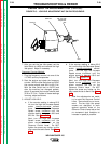
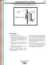
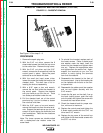
8. To reinstall the brush holder assembly,
depress the spring-loaded brushes into
the holder and slip a suitable non-metal-
lic, fairly stiff retainer through the slots at
the top and bottom of the holder. A cable
tie works well; see Figure F.14. This will
hold the brushes up so that you can eas-
ily install the holder.
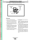
9. With the needle nose pliers, reinstall the
red and the black wires to the appropriate
terminals on the brushes. The red wire is
inboard.
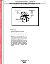
10. Slip the holder into position in the genera-
tor end bracket. Be careful not to loosen
the 2 attached wires.
11. Reinstall and tighten the 2 screws with the
1/4” nut driver.
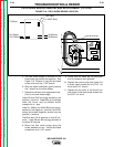
12. Slowly remove the non-metallic retainer
from the brush holder and let the brushes
snap back against the slip rings.
13. Check the wire connections or clearance
and tightness.
14. Snap the brush holder cover back into
position.
TROUBLESHOOTING & REPAIR
F-37 F-37
WELDANPOWER 125