


OUTPUT CHOKE REMOVAL AND REPLACEMENT (continued)
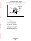
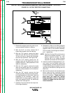
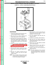
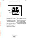
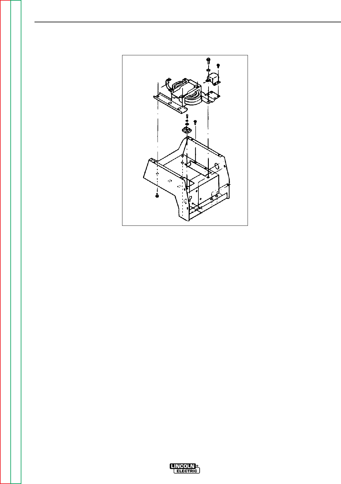
FIGURE F.21 - OUTPUT CHOKE MOUNTING DETAILS
PROCEDURE
1. Remove the engine spark plug wire to pre-
vent accidental kickback or starting.
2. With the 5/16" nut driver, remove the 8
sheet metal screws from the case top.
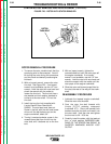
3. With the 5/16" nut driver and 5/16" wrench,
remove the 6 sheet metal screws that hold
the control panel in place. Carefully move
the control panel aside as far as the leads
will allow.
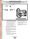
4. Remove the output rectifier bridge. Refer
to "THE OUTPUT RECTIFIER BRIDGE
REMOVAL AND REPLACEMENT" proce-
dure in this section of the manual.
5. With the 9/16" wrench, remove the heavy
choke lead from the positive output termi-
nal.
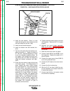
6. With the 1/2" wrench, remove the four
mounting screws that hold the output
choke in place.
NOTE: The two thread forming screws (with
shake-proof lock washers) are used in
the two holes nearest the engine.
7. With the 5/16" nut driver, remove the one
sheet metal screw that holds the choke
assembly to the sheet metal.
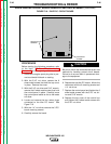
8. Cut any necessary cable ties with the
diagonal cutters.
9. Unfasten any necessary cable restraints.
10. With the 5/16" nut driver, remove the
sheet metal grounding screw and the two
green ground wires.
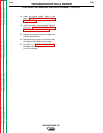
11. Remove the two leads #208 and #209
from the idler solenoid.
12. Remove lead #14 from lead #14A by
pulling apart the quick connect splice.
13. Carefully remove the choke assembly by
lifting up and out.
NOTE: The idler solenoid will be removed
with the choke assembly. Take care to
slide the plunger out from the solenoid
housing.
TROUBLESHOOTING & REPAIR
F-51 F-51
WELDANPOWER 125
Return to Section TOC Return to Section TOC Return to Section TOC Return to Section TOC
Return to Master TOC Return to Master TOC Return to Master TOC Return to Master TOC