


Return to Section TOC Return to Section TOC Return to Section TOC Return to Section TOC
Return to Master TOC Return to Master TOC Return to Master TOC Return to Master TOC
OPERATION
E-2 E-2
WELDANPOWER 125
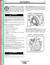
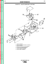
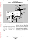
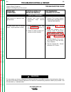
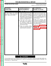
FIGURE E.2 – ENGINE, EXCITATION, ROTOR AND STATOR
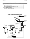
NOTE: Unshaded areas of Block Logic Diagram are the subject of discussion.
ENGINE, EXCITATION, ROTOR
AND STATOR
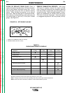
A small voltage developed by the engine magneto is
rectified on the idler P.C. board and fed to the rotating
field coil in the rotor via a brush and slip ring configu-
ration. This excitation (“flashing”) voltage magnetizes
the rotor lamination. The rotor is mechanically cou-
pled to the engine. The rotating magnet induces a
voltage in the stationary windings of the main alterna-
tor (stator).
Three separate and isolated windings are incorporated
in the stator lamination assembly. Each winding set
has a different number of turns, producing different
magnitudes of AC output voltages. The three wind-
ings are the weld winding, the auxiliary power winding
and the field feedback winding. The field feedback
winding provides rotor current during machine opera-
tion, and, through the idle switch, supplies power to
the idler board. The output of the WELDANPOWER
125 is dependent on two criteria: the engine RPM and
the amount of current in the rotor winding.
ENGINE
MECHANICAL
ROTATION
STATOR
ROTOR
STATOR
CHOKE
ROTOR
SLIP
RINGS
CAPACITORS
IDLER
SOLENOID
IDLER
P.C. BOARD
IDLE
SWITCH
RHEOSTAT
HOUR
METER
115 AND 230 VAC
RECEPTACLES
FIELD
RECTIFIER
BRIDGE
MAGNETO
OUTPUT
RECTIFIER
BRIDGE
POSITIVE
OUTPUT
TERMINAL
NEGATIVE
OUTPUT
TERMINAL
+
CURRENT
TRANSFORMER