


Return to Section TOC Return to Section TOC Return to Section TOC Return to Section TOC
Return to Master TOC Return to Master TOC Return to Master TOC Return to Master TOC
OPERATION
B-5 B-5
WELDANPOWER 125
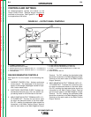
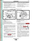
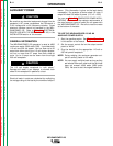
FIGURE B.2 – GASOLINE ENGINE CONTROLS
1. FUEL SHUT-OFF VALVE
2. FUEL TANK AND CAP
3. MUFFLER
4. STOP SWITCH/OIL GARD
®
LIGHT
5. AIR CLEANER
6. IDLER CONTROL SWITCH (NOT SHOWN)
7. CARBURETOR
8. RECOIL STARTER
9. THROTTLE AND CHOKE CONTROLS
10. FUEL MIXTURE ADJUSTMENT SCREW (NOT SHOWN)
11. OIL DRAIN PLUG
12. OIL FILL/DIPSTICK
GASOLINE ENGINE CONTROLS
See Figure B.2 for the location of the following fea-
tures.
1. FUEL SHUTOFF VALVE: Stops the flow of gasoline
from the fuel tank to the carburetor. Should be
closed whenever you are finished using the WEL-
DANPOWER 125. Must be opened before you
start the engine.
2. FUEL TANK AND CAP: Holds 1.6 gallon (6.0 liters)
of unleaded gasoline. Contains a 50 micron fuel
filter molded at the outlet port.
NOTE: If you use any other alternate fuel tank or
supply, be sure to use a recommended in-
line fuel filter.
3. MUFFLER: Reduces engine noise output. Does
not serve as a spark arrester. See SPARK
ARRESTER in the Installation section of this man-
ual.
4. ROCKER STOP SWITCH/OIL GARD
®
LIGHT:
Stops the engine by grounding the ignition circuit.
Glows red when engine oil level is low.
5. AIR CLEANER: Filters intake air to the carburetor.
See ENGINE MAINTENANCE in the Maintenance
section of this manual for details about the specif-
ic type of air cleaner to use.
6. IDLER CONTROL SWITCH: (Not
shown. See item 10, Figure B.1.)
Adjusts the running speed of the
engine. The switch has two positions,
HIGH and AUTO. In HIGH, the
engine runs continuously at high
idle. In AUTO, the idler control
works as follows:
Welding: The engine accelerates to high speed
when the electrode touches the work and strikes a
welding arc. The engine returns to low idle
approximately 12 seconds after welding stops, as
long as no auxiliary power is being drawn.
Auxiliary Power: The engine accelerates to high
speed when power is drawn at the receptacles for
lights or tools. The engine returns to low idle
approximately 12 seconds after demand for auxil-
iary power stops.
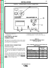
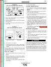
5. GROUND STUD: Provides a connection point for
connecting the machine case to earth ground for
the safest grounding procedure.
6. 20 AMP CIRCUIT BREAKERS (2): Provide sepa-
rate overload current protection for the 115 volt
and 230 volt receptacles.
7. 20 AMP, 230 VOLT RECEPTACLE: Connection
point for supplying 230 volt power to operate one
electrical device.
8. 20 AMP, 115 VOLT DUPLEX RECEPTACLE:
Connection point for supplying 115 volt power to
operate one or two electrical devices.
9. HOUR METER: Records the engine running time
for maintenance purposes.
10. IDLER CONTROL SWITCH: Sets idle speed to
FAST IDLE or AUTOMATIC IDLE.
9
5
8
1
4
2
3
7
11
12