


69
SETTINGS AND ADJUSTMENTS
SECTION 4-34
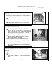
Zero Speed Sensor
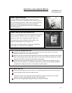
ZERO SPEED SENSOR
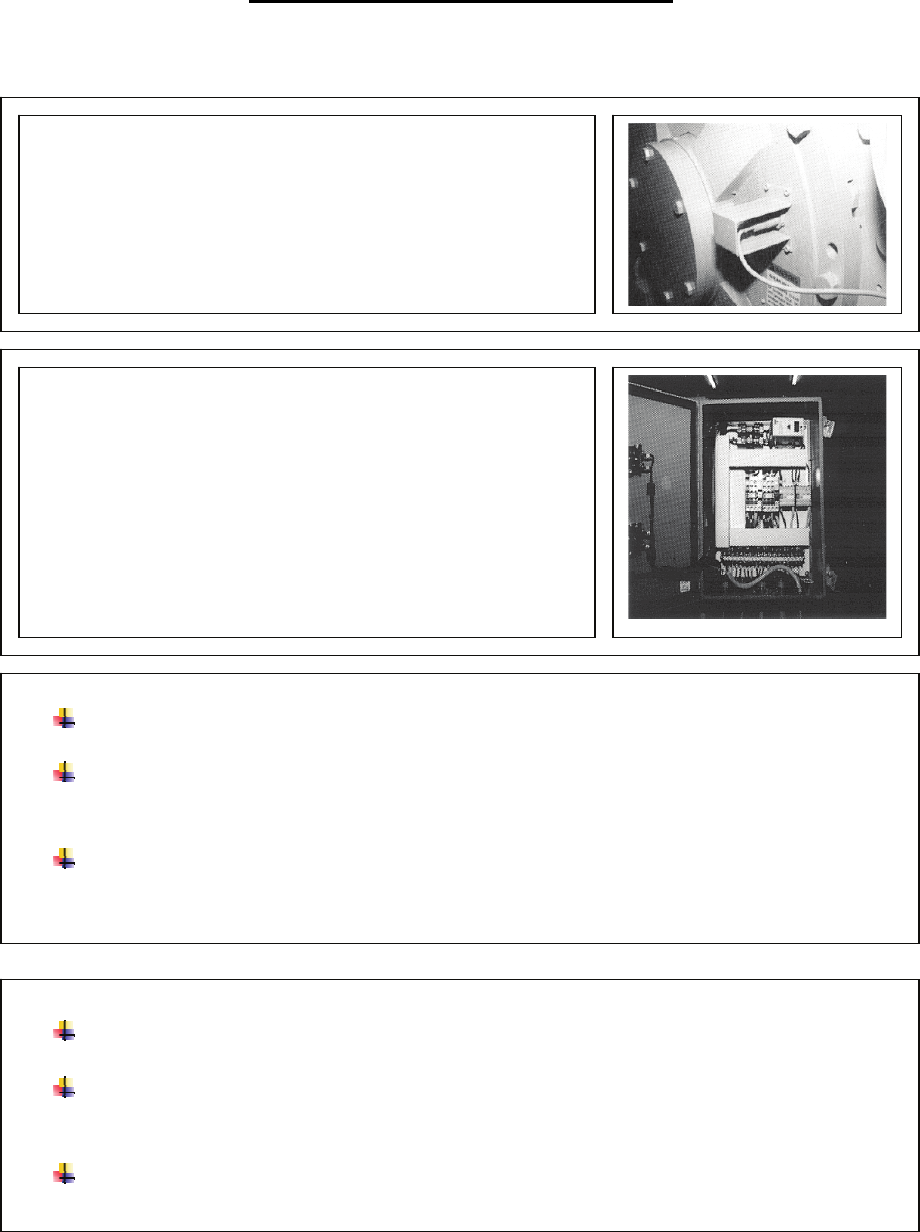
The zero speed sensor detects the motion of the rotor
assembly. The sensor is interlocked to the control circuits of
the two machine jackscrews. If the rotor is turning, then the
jackscrews should not operate. If you notice that the
jackscrews are operational while the rotor is turning, check
the following areas.
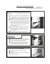
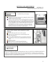
ZERO SPEED SENSOR OPERATION
There is a red pilot light on the sensor amplifier located in the
control console. When the rotor is in motion, the red pilot
light is lit. If the rotor is stopped, the pilot light is out.
The sensor has a green pilot light which, when it is lit,
indicates that the power to the sensor is on.
If the rotor is in motion and the red light is off while the
green light is on, check the sensor position.
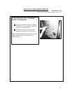
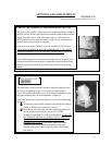
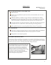
ADJUST THE SENSOR POSITION
Disconnect and remove the sensor wire from the control console. Refer to the wiring
diagram supplied with your manual for details.
Remove the sensor from the bearing housing. Measure the length of the thread in the tapped
hole on the bearing housing where the sensor was mounted. Using this dimension, measure
from the end of the sensor and set the locknut at this point.
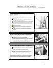
Thread the sensor into the hole and lock it in position. Turn the rotor assembly slowly by
hand to be sure that there is no interference between the sensor and the rotating members.
Complete the wiring between the sensor and the control console.
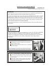
CONTROL CIRCUIT
If the green pilot light is off at all times or if re-positioning the sensor does not correct the
sensor operation, then check the control circuit.
Check the control circuit logic between the hydraulic system or jackscrews, the safety
switches, the zero speed amplifier, and the zero speed sensor.
Refer to the wiring diagram supplied with your manual for details.