


Appendix B Verification and Calibration
100 Series N5700 User’s Guide
4 With the electronic load in CV mode, set it for the output’s full-
scale voltage. The CC annunciator on the front panel must be on.
If it is not, adjust the load so that the voltage drops slightly.
5 Divide the voltage drop (DVM reading) across the current
monitoring resistor by its resistance to convert to amps and
record this value (Iout).
6 Short the electronic load. Divide the voltage drop (DVM reading)
across the current shunt by its resistance to convert to amps and
record this value (Iout). The difference in the current readings in
steps 4 and 5 is the load effect, which should not exceed the
value listed in the test record card for the appropriate model
under CC Load Effect.
CC Source Effect
Test category = performance
This test measures the change in output current that results from a
change in AC line voltage from the minimum to maximum value
within the line voltage specifications.
1 Turn off the power supply and connect the ac power line through
a variable voltage transformer or AC source.
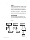
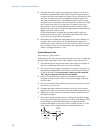
2 Connect the current shunt, DVM, and electronic load as shown in
figure B. Connect the DVM directly across the current shunt. Set
the variable voltage transformer to nominal line voltage.
3 To ensure that the values read during this test are not the
instantaneous measurement of the AC peaks of the output
current ripple, several DC measurements should be made and
averaged. If you are using an Agilent 3458A, you can set up the
voltmeter to do this automatically. From the instrument’s front
panel, program 100 power line cycles per measurement. Press
NPLC 100 ENTER.
4 Turn on the power supply and program the output current to its
full-scale value and the output voltage to its maximum
programmable value (Vmax).
5 With the electronic load in CV mode, set it for the output’s full-
scale voltage. The CC annunciator on the front panel must be on.
If it is not, adjust the load so that the voltage drops slightly.
6 Adjust the transformer to the lowest rated line voltage (85 VAC
for 100/120 nominal line; 170 VAC for 200/240 nominal line).
7 Divide the voltage drop (DVM reading) across the current
monitoring resistor by its resistance to convert to amps and
record this value (Iout).
8 Adjust the transformer to the highest rated line voltage (132 VAC
for 100/120 nominal line; 265 VAC for 200/240 nominal line).
9 Divide the voltage drop (DVM reading) across the current shunt
by its resistance to convert to amps and record this value (Iout).
The difference between the DVM reading in steps 6 and 8 is the
source effect, which should not exceed the value listed in the test
record card for the appropriate model under CC Source Effect.