


2 Installation
28 Series N5700 User’s Guide
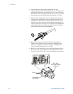
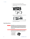
Grounding the Output
The output of the power supply is isolated from earth ground. Either
positive or negative voltages can be obtained from the output by
grounding (or "commoning") one of the output terminals. Always use
two wires to connect the load to the output regardless of where or
how the system is grounded.
To avoid noise problems caused by common-mode current flowing
from the load to ground, it is recommended to ground the output
terminal as close as possible to the power supply chassis ground
.
WARNING
SHOCK HAZARD For models up to 60VDC rated output, no point shall be more
than +/-60VDC above/below chassis ground. For models > 60VDC rated
output, no point shall be more than +/-600VDC above/below chassis ground.
There is also a potential shock hazard at the IEEE/LAN/USB ports when
using power supplies with rated or combined voltages > 400VDC with the
positive output of the power supplies grounded. Do not connect the positive
output to ground when using the IEEE/LAN/USB under the above conditions.
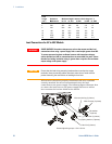
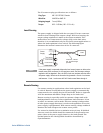
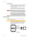
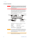
Parallel Connections
CAUTION
Only power supplies that have identical voltage and current ratings can be
connected in parallel.
Up to four units of the same voltage and current rating can be
connected in parallel to provide up to four times the output current
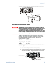
capability. Refer to the following figures for typical connections of
parallel power supplies using either local or remote sensing. The
figures show two units, however, the same connection method
applies for up to four units.
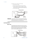
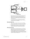
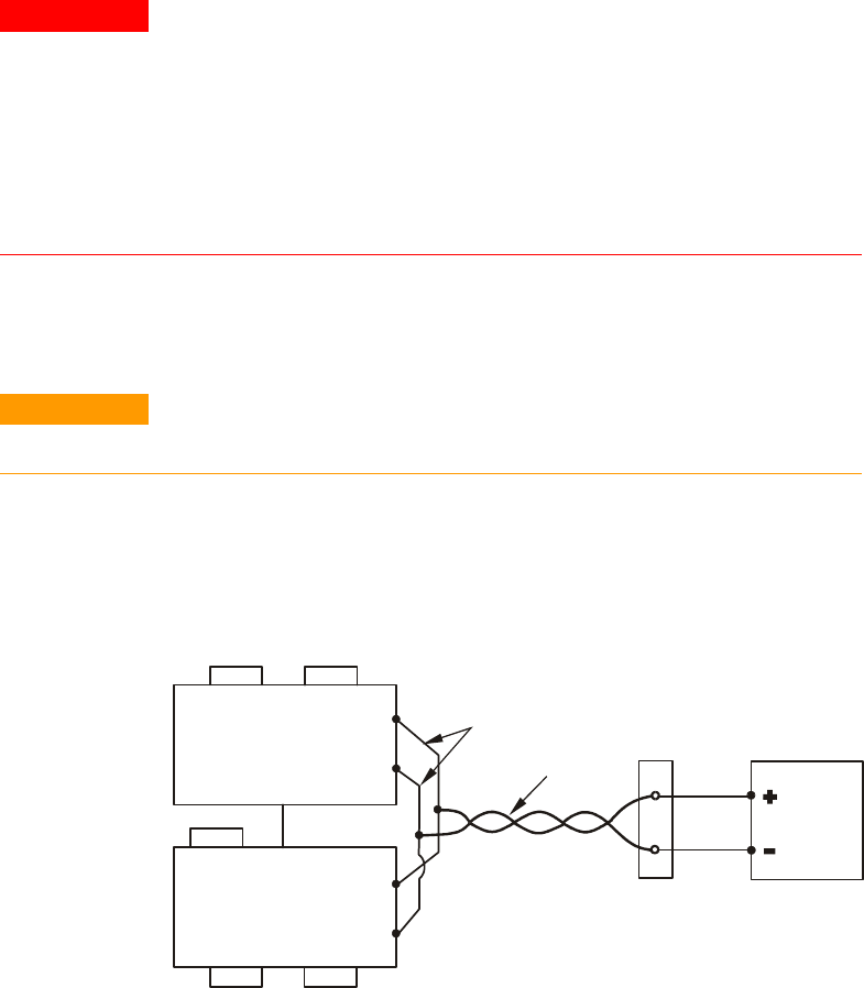
Local Sensing
+V
-V
+V
-V
+S+LS-S -LS
+S+LS-S -LS
MASTER
POWER SUPPLY
SLAVE
POWER SUPPLY
LOAD
J1-25
J1-10
Parallel
Current Program
As short as possible
Twisted
pair
J1-8
J1-12