


2 Installation
20 Series N5700 User’s Guide
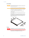
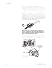
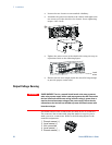
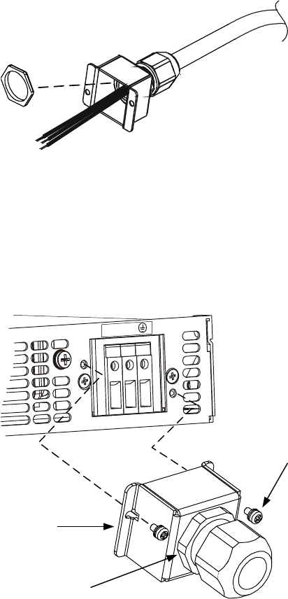
• Unscrew the base of the strain relief from the wire
compression nut. Place the locknut inside the AC input cover
with the flat side of the nut against the cover. Insert the base
through the outside opening of the AC input cover. Screw the
base securely onto the locknut from the outside (17 ft-lbs).
• Slide the wire compression nut over the AC cable. Insert the
stripped wires through the strain relief base until the outer
cable jacket is flush with the inside edge of the base. Place a
wrench on the base to keep it from turning. Now tighten the
compression nut to the base (14-16.2 ft-lbs) while holding the
cable in place. Now the cable is securely fastened inside the
strain relief. Refer to the following figure.
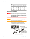
• Route the AC wires to the input connector terminals as
required. To connect the wires, loosen the terminal screw,
insert the stripped wire into the terminal, and tighten the
screw securely to between 4.4–5.3 in-lbs.
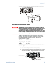
• Route the wires inside the cover to prevent pinching. Fasten
the cover to the unit using the M3 x 8mm pan head screws
provided (4.8 in-lbs). Refer to the following figure for details.
L
N
Cover
Assembled
Strain Relief
M3 x 8mm
Pan Head Screws
(2 places)