


Installation 2
Series N5700 User’s Guide 21
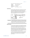
Connecting the Load
WARNING
SHOCK HAZARD Turn off AC power before making rear panel connections.
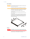
All wires and straps must be properly connected with screws securely
tightened.
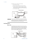
As further explained in this section, the following factors should be
considered when selecting wiring to connect the load to the power
supply:
• Current carrying capacity of the wire
• Insulation rating of the wire should be at least equivalent to
the maximum output voltage of the power supply
• Maximum wire length and voltage drop
• Noise and impedance effects of the load wiring
Wire Size
WARNING
FIRE HAZARD To satisfy safety requirements, select a wire size heavy
enough not to overheat while carrying the power supply load current at the
rated load, or the current that would flow in the event the load wires were
shorted, whichever is greater.
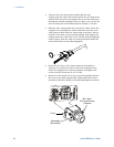
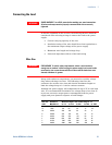
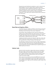
Along with conductor temperature, you must also consider voltage
drop when selecting wire sizes. The following chart lists the
resistance for various wire sizes and also the maximum lengths to
limit the voltage drop to 1.0 volt for various currents.
Although the power supply will compensate for up to 5V in each load
wire, it is recommended to minimize the voltage drop to less than 1V
to prevent excessive output power consumption from the power
supply and poor dynamic response to load changes.
Wire size
AWG
Resistance
Ω
ΩΩ
Ω/1000 foot
Maximum length in feet to limit voltage to 1 V
for 5 A for 10 A for 20A for 50A for 150A
14 2.526 80 40 20 8 2
12 1.589 120 60 30 12 3.4
10 0.9994 200 100 50 20 6
8 0.6285 320 160 80 32 10
6 0.3953 500 250 125 50 16
4 0.2486 800 400 200 80 26
2 0.1564 1200 600 300 125 40
0 0.0983 2000 1000 500 200 68