


2 Installation
26 Series N5700 User’s Guide
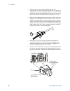
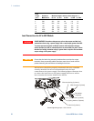
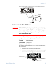
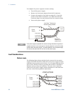
To configure the power supply for remote sensing:
• Turn off the power supply.
• Remove the local sense jumpers from the J2 connector.
• Connect the negative sense lead to terminal 5 (-S) and the
positive sense lead to terminal 1 (+S). Make sure that the
connector plug is securely inserted into the connector body.
• Turn on the power supply.
NOTE
If the power supply is operated with remote sensing and either the positive or
negative load wire is not connected, an internal protection circuit will activate
and shut down the power supply. To resume operation, turn the power supply
off, connect the open load wire, and turn on the power supply.
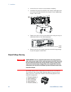
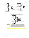
Load Considerations
Multiple Loads
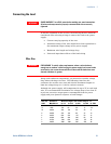
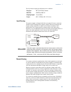
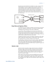
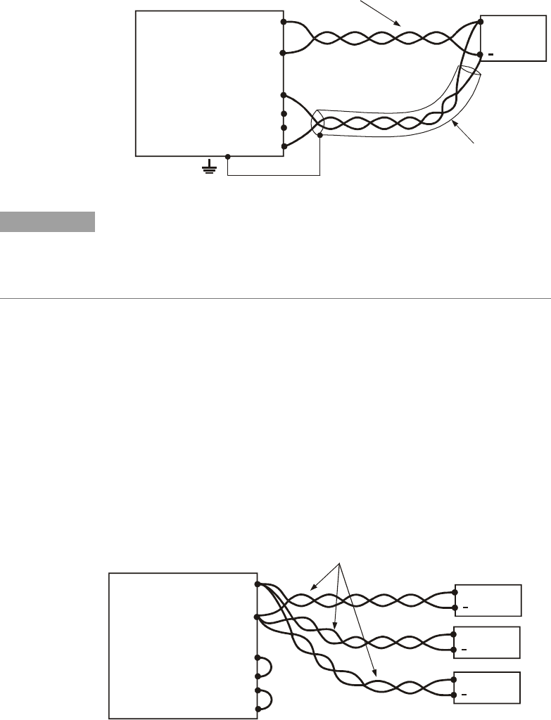
The following figure shows multiple loads connected to one power
supply. Each load should be connected to the power supply’s output
terminals using separate pairs of wires. It is recommended that each
pair of wires will be as short as possible and twisted or shielded to
minimize noise pick-up and radiation. The sense wires should be
connected to the power supply output terminals or to the load with
the most critical load regulation requirement.
-
-
Rem.sense
Local sense
ocal sense
Rem.sense
+L
+
Load lines, twisted pair,
shortest length possible.
+V
-V
Load#1
+
Load#3
+
Load#2
+
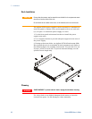
Power
Supply
-
-
Rem.sense
Local sense
ocal sense
Rem.sense
+L
+
Sense lines.
Twisted pair or
+V
-V
Load
+
Power
Supply
Load lines. Twisted pair
shortest length possible.
shielded wires.