


1 Quick Reference
12 Series N5700 User’s Guide
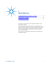
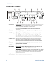
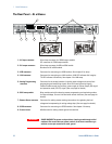
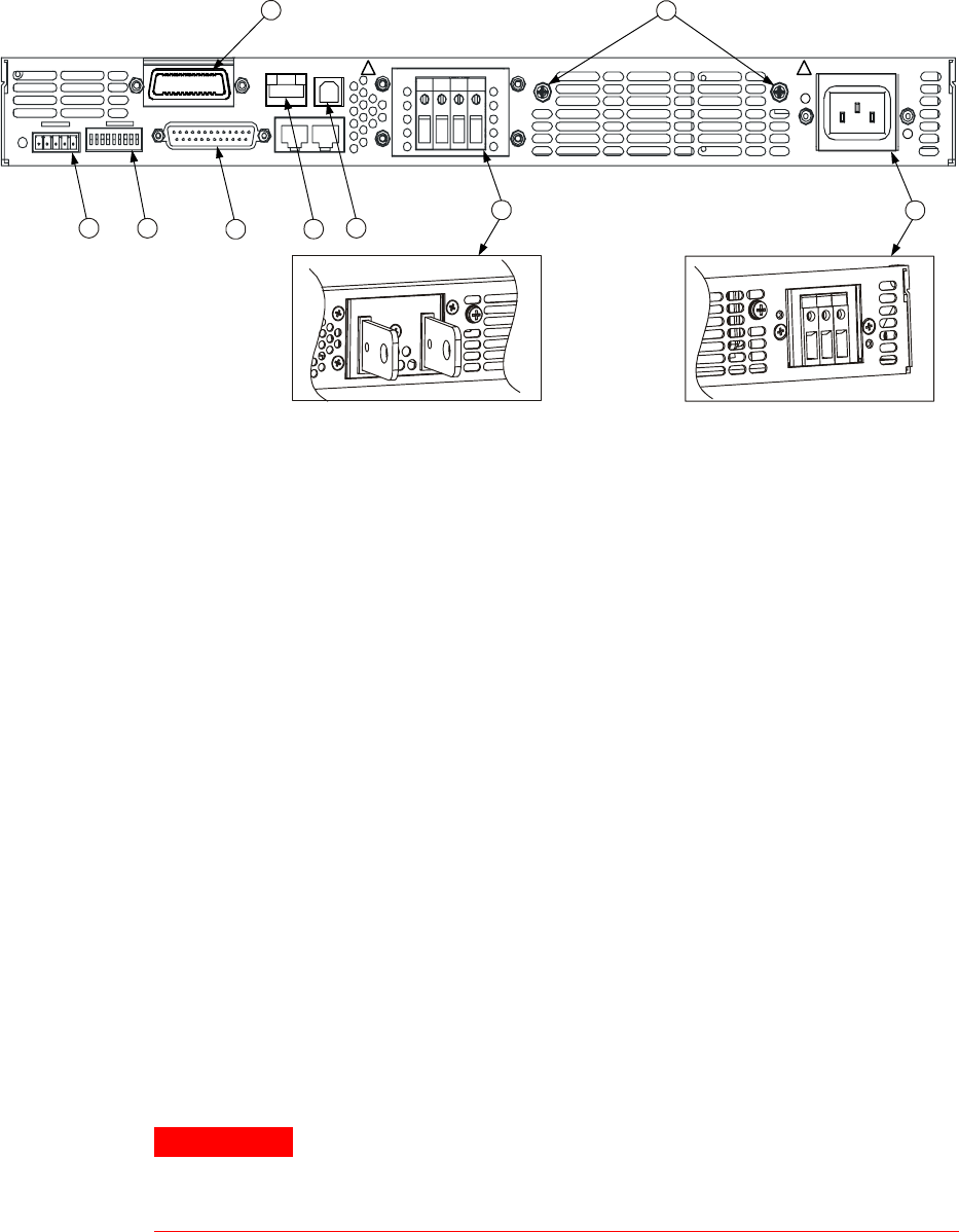
The Rear Panel – At a Glance
9
5
7 3
8
4
6
1
2
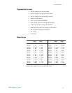
750W
1500W6V - 60V
80V - 600V
AC INPUT
ON
OFF
+V -V
NOT ACTIVE
J2
SW1
GPIB
ANALOG PROGRAMMING
+S+LS NC -LC-S
1 2 3 4 5 6 7 8 9
10/100 Ethernet
LINK TX
J1
! !
1 – AC input connector Wire clamp connector for 1500W output models.
IEC connector for 750W output models.
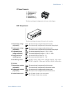
2 – DC output connector Wire clamp connector for 80V to 600V models.
Bus bars for 6V to 60V models.
3 – USB connector Connector for connecting to a USB interface. See chapter 4 for setup.
4 – LAN connector Connector for connecting to a LAN interface. LINK LED indicates link integrity.
TX LED indicates LAN activity. See chapter 4 for LAN setup.
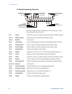
5 – Analog Programming
connector
Connector for the analog interface. Includes output voltage and current limit
programming and monitoring signals, Shut-Off control (electrical signal),
Enable/Disable control (dry-contact), power supply ok (Power Supply OK) signal
and operation mode (CV/CC) signal. (See next page for details)
6 – SW1 setup switch Nine-position switch for selecting remote programming and monitoring modes
for Output Voltage, Current Limit and other control functions. (See next page for
details)
7 – Remote Sense connector Connector for making remote sensing connections for regulating the load
voltage and compensating for wiring voltage drop. (See next page for details)
8 – GPIB connector Connector for connecting to a GPIB interface. See chapter 4 for setup.
9 – Ground screw M4x8 screws for making chassis ground connections
WARNING
SHOCK HAZARD The power cord provides a chassis ground through a third
conductor. Be certain that your power outlet is of the three-conductor type
with the correct pin connected to earth ground