


Installation 2
Series N5700 User’s Guide 23
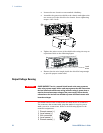
Install the shield after you have finished connecting the load wires.
Load Connections for 80V to 600V Models
WARNING
SHOCK HAZARD Hazardous voltages may exist at the outputs and the load
connections when using a power supply with a rated output greater than 40V.
To protect personnel against accidental contact with hazardous voltages,
ensure that the load and its connections have no accessible live parts. Ensure
that the load wiring insulation rating is greater than or equal to the maximum
output voltage of the power supply.
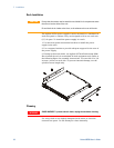
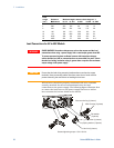
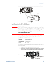
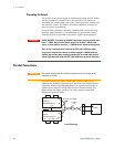
The 80V to 600V models have a four-terminal wire clamp output
connector. The two left terminals are the positive outputs and the
two right terminals are the negative outputs. The connector
specifications are as follows:
Wire Size:
AWG 18 to AWG 10
Stripping Length:
10 mm (0.39 in.)
Torque:
6.5 - 7 in-lb.
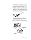
The following instructions describe how to connect the load wires to
the power supply:
• Strip wires back approximately 10 mm (0.39 in).
• Loosen the connector terminal screws and insert the stripped
wires into the terminal. Tighten the terminal screw securely.
Shield
Load wires
Negative (-)
Output/Retur
n
Positive Output (+)
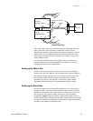
+V
-V