


Verification and Calibration Appendix B
Series N5700 User’s Guide 95
Measurement Techniques
Electronic Load
Many of the test procedures require the use of a variable load capable
of dissipating the required power. If a variable resistor is used,
switches should be used to either; connect, disconnect, or short the
load resistor. For most tests, an electronic load can be used. The
electronic load is considerably easier to use than load resistors, but it
may not be fast enough to test transient recovery time and may be
too noisy for the noise (PARD) tests.
Fixed load resistors may be used in place of a variable load, with
minor changes to the test procedures. Also, if computer controlled
test setups are used, the relatively slow (compared to computers and
system voltmeters) settling times and slew rates of the power supply
may have to be taken into account. "Wait" statements can be used in
the test program if the test system is faster than the power supply.
Current-Monitoring Resistor
The 4-terminal current shunt is used to eliminate output current
measurement error caused by voltage drops in the load leads and
connections. It has special current-monitoring terminals inside the
load connection terminals. Connect the voltmeter directly to these
current-monitoring terminals.
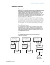
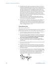
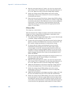
Test Set-up
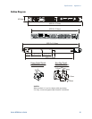
The following figure illustrates the test set-up used for the
verification procedures.
A.
Electronic load
or resistor
DC voltmeter,
scope, or
rms voltmeter
Load
Resistor
+
+
+
B.
Differential
amplifier
C.
Scope or
rms voltmeter
Current
shunt
+
DC voltmeter,
scope, or
rms voltmeter
+
Electronic load
or resistor
50 50
output
50 ohm
termination
input
BNC
BNC
BNC
+V -V
Power Supply
+S +LS -LS -S
+V -V
Power Supply
+S +LS -LS -S
+V -V
Power Supply
+S +LS -LS -S