


Operating the Power Supply Locally 3
Series N5700 User’s Guide 37
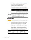
CV/CC Mode Crossover
If the power supply is in constant voltage mode and the load current
increases above the current limit setting, the power supply switches
to constant current mode. If the load decreases below the current
limit setting, the power supply switches to constant voltage mode.
CV/CC Signal
CAUTION
Do not connect the CV/CC signal to a voltage source higher than 30VDC.
Always connect the CV/CC signal to the voltage source with a series resistor to
limit the sink current to less than 10mA.
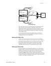
The CV/CC signal available on the J1 connector indicates the
operating mode of the power supply. The CV/CC signal is an open
collector output with a 30V parallel zener at J1 pin 13, referenced to
common at J1 pin 12. J1 pin 12 is connected internally to the –S
terminal. When the power supply operates in constant voltage mode,
CV/CC output is open. When the power supply operates in constant
current mode, CV/CC signal output is low (0 - 0.6V), with maximum
10mA sink current.
Protection Functions
Over-Voltage Protection
The over-voltage protection protects against over-voltage conditions
on the output. If the output voltage attempts to exceed the
programmed limit in response to an analog programming signal or in
the event of a power supply failure, the over-voltage protection
circuit will protect the load by disabling the output. The voltage is
monitored at the sense terminals, thus providing the protection level
directly at the load. Upon detection of an over-voltage condition, the
output is disabled, the display shows OVP, the PROT indicator blinks,
and OV is set in the Questionable Condition status register.
Adjustment of the over-voltage setting can be made when the output
is enabled (On) or disabled (Off). To set the OVP level, press the
OVP/UVL button so that the display indicates OUP. The display will
show the OVP setting. Rotate the voltage knob to adjust the OVP level.
The display will show OVP and the setting value for another five
seconds and then return to its previous state.
The OVP settings are limited at the minimum level to approximately
5% above the output voltage setting. Attempting to adjust the OVP
below this limit will result in no response to the adjustment attempt.
Refer to Appendix A for the maximum OVP settings.
Use one of the following methods to reset the OVP circuit after it
activates. If the condition that caused the over-voltage shutdown is
still present, the OVP circuit will turn the output off again.