


Verification and Calibration Appendix B
Series N5700 User’s Guide 97
CV Source Effect
Test category = performance
This test measures the change in output voltage that results from a
change in AC line voltage from the minimum to maximum value
within the line voltage specifications.
1 Turn off the power supply and connect the ac power line through
a variable voltage transformer.
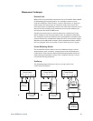
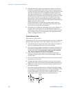
2 Connect a DVM and an electronic load as shown in figure A. Set
the variable voltage transformer to nominal line voltage.
3 Turn on the power supply and program the output current to its
maximum programmable value (Imax) and the output voltage to
its full-scale value.
4 Set the electronic load for the output’s full-scale current. The CV
annunciator on the front panel must be on. If it is not, adjust the
load so that the output current drops slightly.
5 Adjust the transformer to the low-line voltage (85 VAC for
100/120 nominal line; 170 VAC for 200/240 nominal line).
6 Record the output voltage reading from the DVM.
7 Adjust the transformer to the high-line voltage (132 VAC for
100/120 nominal line; 265 VAC for 200/240 nominal line).
8 Record the output voltage reading on the DVM. The difference
between the DVM reading in steps 6 and 8 is the source effect,
which should not exceed the value listed in the test record card
for the appropriate model under CV Source Effect.
CV Noise
Test category = performance
Periodic and random deviations in the output combine to produce a
residual AC voltage superimposed on the DC output voltage. This
residual voltage is specified as the rms or peak-to-peak output
voltage in the frequency range specified in Appendix A.
1 Turn off the power supply and connect the load resistor,
differential amplifier, and an oscilloscope (ac coupled) to the
output as shown in figure C. Use the indicated load resistor for
750W outputs; use the indicated load resistor for 1500W outputs.
2 As shown in the diagram, use two BNC cables to connect the
differential amplifier to the + and − output terminals. Each cable
should be terminated by a 50 Ω resistor. The shields of the two
BNC cables should be connected together. Connect the output of
the differential amplifier to the oscilloscope with a 50 Ω
termination at the input of the oscilloscope.
3 Set the differential amplifier to multiply by ten, divide by one,
and 1 Megohm input resistance. The positive and negative inputs
of the differential amplifier should be set to AC coupling. Set the
oscilloscope’s time base to 5 ms/div, and the vertical scale to 10
mV/div. Turn the bandwidth limit on (usually 20 or 30 MHz), and
set the sampling mode to peak detect.