


3 Operating the Power Supply Locally
42 Series N5700 User’s Guide
Power Supply OK Signal
The Power Supply OK signal on the J1 connector indicates a fault
condition in the power supply. J1 pin 16 is a TTL output signal. Pins
2 and 3, which are connected internally, are the signal common. All
pins are optically isolated from the power supply output. With no
fault, Power Supply OK is high, with a maximum source current of
2mA. When a fault occurs, Power Supply OK is low, with a maximum
sink current of 1mA. The following faults set this signal low:
Over-voltage protection Enable/Disable signal true
Over-current protection Shut Off signal true
Over-temperature protection Remote interface failure
AC line failure Output turned off
Daisy-Chained Output Shut-down
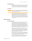
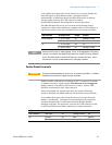
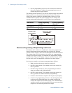
It is possible to configure a multiple power supply system to shut
down all the units when a fault condition occurs in one of the units.
SW1 setup switch 5 must be in the Down position to enable the daisy-
chain operation. Other switches are unaffected by this setting.
If a fault occurs in one unit, its Power Supply OK signal is set low and
its display will indicate the fault. The other units shut off with their
displays indicating SO. When the fault condition is cleared, all units
will recover according to their Safe-Start or Auto-Restart settings.
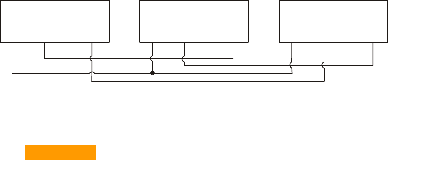
The following figure shows three units daisy-chained - the same
connection method can be used with additional units. The Shut Off
and Power Supply OK signals are referenced to Chassis Common (J1
pins 2 and 3).
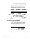
Analog Programming of Output Voltage and Current
CAUTION
J1 pin 12, pin 22, and pin 23 are internally connected to the negative sense
terminal. Do not reference these pins to any terminal other than the negative
sense terminal, as it may damage the unit.
In Local mode, the output voltage and current is programmed with
the front panel VOLTAGE and CURRENT knobs or over the remote
interface. In Analog mode, the output voltage and current can be
programmed either by an analog voltage or by resistors connected to
the rear panel J1 connector.
POWER SUPPLY
#
1
J1-2,3 J1-16 J1-16J1-16J1-15
Supply OK
POWER SUPPLY
#
2
J1-2,3 J1-15
POWER SUPPLY
#3
J1-2,3 J1-15
Shut OffCom Shut OffSupply OKCom Com Supply OK Shut Off