


Quick Reference 1
Series N5700 User’s Guide 13
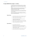
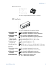
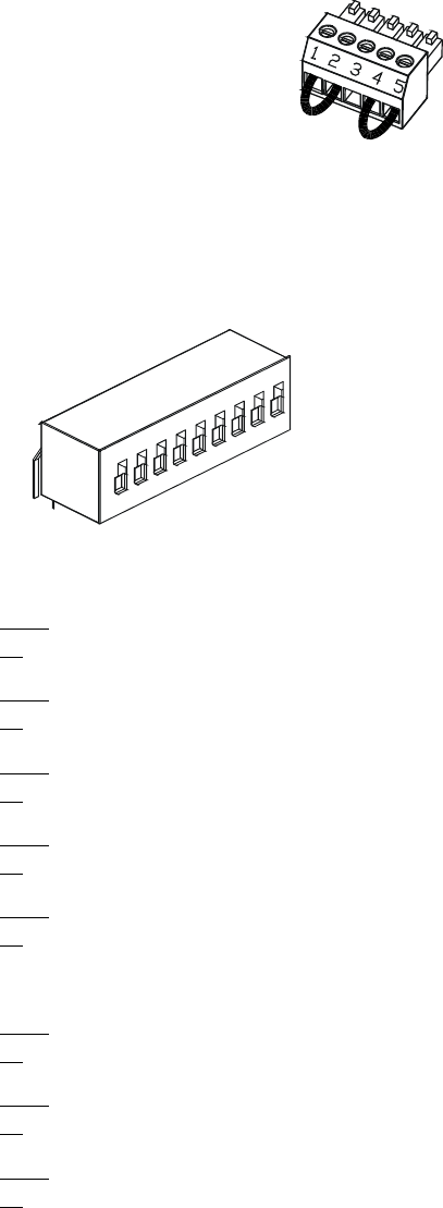
J2 Sense Connector
1 – Remote sense (+)
2 – Local sense (+)
3 – Not used
4 – Local sense (–)
5 – Remote sense (–)
The factory-shipped configuration is shown in the figure.
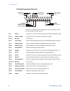
SW1 Setup Switch
The factory-shipped setting is Down for all switches.
1 – Output voltage, voltage
programming
Down
: The output voltage is programmed by the front panel.
Up
: The output voltage is programmed by the external voltage signal.
2 – Output current, voltage
programming
Down
: The output current is programmed by the front panel.
Up
: The output current is programmed by the external voltage signal.
3 – Programming range
(voltage/resistance)
Down
: The remote programming range is: 0 – 5V / 0 – 5KΩ.
Up
: The remote programming range is: 0 – 10V / 0 – 10KΩ.
4 – Voltage and Current
monitoring range
Down
: The remote monitoring range is: 0 – 5V.
Up
: The remote monitoring range is: 0 – 10V.
5 – Shut-Off Logic Select Down
: OUT OFF = Low (0 – 0.6V) or short; OUT ON = High (2V – 15V) or open.
Up
: OUT OFF = High (2V – 15V) or open; OUT ON = Low (0 – 0.6V) or short.
6 – Not Used
7 – Output voltage, resistive
programming
Down
: The output voltage is programmed by the front panel.
Up
: The output voltage is programmed by the external resistor.
8 – Output current, resistive
programming
Down
: The output current is programmed by the front panel.
Up
: The output current is programmed by the external resistor.
9 – Enable/Disable control Down
: The J1 Enable+/Enable– pins are not active.
Up
: The J1 Enable+/Enable– pins are active.
1
2
3
4
5
6
7
8
9