


3 Operating the Power Supply Locally
40 Series N5700 User’s Guide
Output On/Off Controls
The Output On/Off controls turn the power supply output on or off.
This can be done with the front panel OUT ON button or from the
rear panel J1 connector. With the output off, adjustments can be
made to the power supply or the load without shutting off AC power.
OUT ON button
The OUT ON button can be pressed at any time to enable or disable
the power supply output. When the output is disabled, the output
voltage and current go to zero and the display shows OFF.
Safe-Start and Auto-Restart
The power supply can be programmed to have either the last
operating settings (Auto-Restart) or the reset settings (Safe-Start)
apply at turn-on. Press and hold the OUT ON button to select between
Safe-Start and Auto-Restart modes. The display continuously cycles
between SAF and AUT every three seconds. Releasing the OUT ON
button while one of the modes is displayed, selects that mode.
In Safe-Start mode, the power supply turns on with the reset
settings (see chapter 5 under “*RST”). The output is disabled and the
output voltage and current are zero. This is the factory default.
In Auto-Restart mode, the power supply restores the operating
settings that were saved when it was last turned off (see below). The
output is either enabled or disabled according to its last setting.
Output On/Off state UVL level
Output voltage setting OCP setting
Output current setting Locked/Unlocked front panel
OVP level Start-up mode
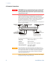
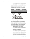
Output Shut-Off Terminals
Output Shut-Off (SO) terminals are available on the J1 connector to
enable or disable the power supply output. This function is edge-
triggered. J1 pin 15 is the Shut-Off input, and pins 2 and 3, which
are connected internally, are the signal common. All pins are
optically isolated from the power supply output. The Shut-Off input
accepts a 2.5V-to-15V signal or an open/short contact to enable or
disable the output. The Shut-Off control logic is selected by SW1
setup switch 5.
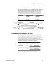
When an on-to-off transition is detected at the Shut-Off input, the
Shut-Off function enables or disables the output according to the
signal level or the open/short applied to J1 pin 15. When the output
has been disabled by the Shut-Off function, the display shows SO to
indicate the output is disabled.