


2 Installation
22 Series N5700 User’s Guide
Cross
section
(mm
2
)
Resistance
Ω
ΩΩ
Ω/kilometer
Maximum length in meters to limit voltage to 1 V
for 5 A for 10 A for 20A for 50A for 150A
2.5 8.21 24.0 12.0 6.0 2.4 0.8
4 5.09 39.2 18.6 9.8 4.0 1.4
6 3.39 59.0 29.4 14.8 5.8 2.0
10 1.95 102 51.2 25.6 10.2 3.4
16 1.24 160 80.0 40.0 16.0 5.4
25 0.795 250 125 62.0 25.2 8.4
35 0.565 354 177 88.0 35.4 11.8
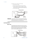
Load Connections for 6V to 60V Models
WARNING
SHOCK HAZARD Hazardous voltages may exist at the outputs and the load
connections when using a power supply with a rated output greater than 40V.
To protect personnel against accidental contact with hazardous voltages,
ensure that the load and its connections have no accessible live parts. Ensure
that the load wiring insulation rating is greater than or equal to the maximum
output voltage of the power supply.
CAUTION
Ensure that the load wiring mounting hardware does not short the output
terminals. Heavy connecting cables must have some form of strain relief to
prevent loosening the connections or bending the bus-bars.
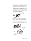
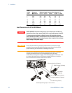
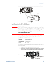
All load wires should be properly terminated with wire terminals
securely attached. Do not use unterminated wires for load
connections at the power supply. The following figures illustrate how
to connect the load wires to the power supply bus-bars as well as
how to mount the bus-bar shield to the chassis.
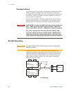
M8x15 screw (2 places)
Hex Nut (2 places)
Flat washer (2 places)
Spring washer (2 places)
Wire terminal lug (2 places)
Flat washer
(2 places)
Screws tightening torque: 104-118 in-lb.