


Installation 2
Series N5700 User’s Guide 29
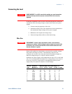
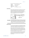
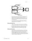
Remote Sensing
One of the units operates as a master and the remaining units are
slaves. The slave units operate as controlled current sources
following the master output current. In remote operation, only the
master unit can be programmed by the computer while the slave
units may be connected to the computer for voltage, current and
status readback only.
It is recommended that each unit supplies only up to 95% of its
current rating because of the imbalance that may be caused by
cabling and connections voltage drops.
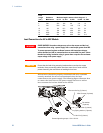
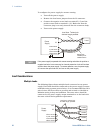
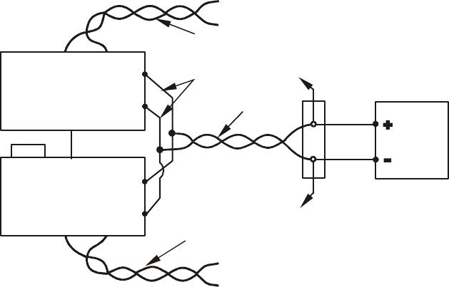
Setting up the Master Unit
Connect the sensing circuit for either local or remote sensing as
shown in the previous figures. Set the master unit output voltage to
the desired voltage. Program the current limit to the desired load
current limit divided by the number of parallel units. During
operation, the master unit operates in constant voltage mode,
regulating the load voltage at the programmed output voltage.
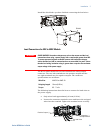
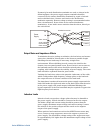
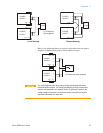
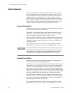
Setting up the Slave Units
Set the rear panel setup switch SW1 position 2 to it’s up position.
Connect J1 pin 10 (Current Program) of the slave unit to J1 pin 25
(Parallel) of the master unit. Also connect a short between J1 pin 8
and J1 pin 12. The output voltage of the slave units should be
programmed higher than the output voltage of the master unit to
prevent interference with the master unit’s control. The current limit
of each unit should be programmed to the desired load current limit
divided by the number of parallel units.
+V
-V
+V
-V
+S-S
+S-S
MASTER
POWER SUPPLY
SLAVE
POWER SUPPLY
+S
-S
+S
+S
-S
-S
LOAD
J1-25
J1-10
Parallel
Current Program
As short as possible
Twisted
pair
Twisted
pair
Twisted
pair
J1-8
J1-12