


Operating the Power Supply Locally 3
Series N5700 User’s Guide 39
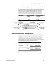
Over-Temperature Protection
The over-temperature protection circuit shuts down the power
supply before the internal components can exceed their safe internal
operating temperature. This can occur if there is a cooling fan failure.
When an OTP condition occurs, the output is disabled, the display
shows O7P, the PROT indicator blinks, and the OT status bit is set in
the Questionable Condition status register. Resetting the OTP circuit
can be automatic (non-latched) or manual (latched) depending on the
Safe-Start or Auto-Restart mode.
In Safe-Start mode, the OTP circuit is latched. The display continues
to show O7P and the PROT indicator continues to blink. To reset the
OTP circuit, press the OUT ON button.
In Auto-Restart mode, the OTP circuit is non-latched. The power
supply returns to its last setting automatically when the over-
temperature condition is removed.
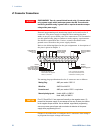
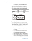
Power-Fail Protection
If the AC power stops briefly, but returns before the power supply
has reset, the power-fail protection circuit trips and the PF status bit
is set in the Questionable Condition status register. Resetting the
power-fail protection can be automatic (non-latched) or manual
(latched), depending on the Safe-Start or Auto-Restart mode.
In Safe-Start mode, the output of the power supply is Off, as specified
by the reset state when AC power returns. In Auto-Restart mode, the
power supply recovers its last settings when AC power returns.
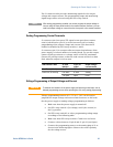
Front Panel Lock-Out
The front panel controls can be locked to protect from accidental
power supply parameter change. Press and hold the LIMIT button to
toggle between Locked front panel and Unlocked front panel. The
display will cycle between LFP and UFP. Releasing the LIMIT button
while one of the modes is displayed, selects that mode.
In Unlocked front panel mode, the front panel controls are enabled
to program and monitor the power supply parameters.
In Locked front panel mode, the VOLTAGE and CURRENT knobs,
the OCP/488 button, and the OUT ON button are disabled
The power supply will not respond to attempts to use these controls.
The display will show LFP to indicate that the front panel is locked.
The OVP/UVL button remains active to preview the OVP and UVL
setting. The LIMIT button also remains active to preview the output
voltage and current setting or to unlock the front panel.
NOTE
This function operates independently of the SCPI SYST:COMM:RLST command.
If the front panel has been locked from the front panel, it cannot be unlocked by
SYST:COMM:RLST. Conversely, if the front panel has been locked by
SYST:COMM:RLST, it cannot be unlocked from the front panel.