


Operating the Power Supply Locally 3
Series N5700 User’s Guide 45
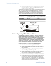
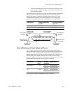
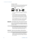
• Set the programming resistors to the desired resistance and
turn the power supply on. Adjust the resistors to change the
power supply output.
The analog control circuits let you set the output voltage and current
limit up to 5% over the model-rated maximum value. The power
supply will operate within the extended range, however it is not
recommended to operate the power supply over its voltage and
current rating, and performance in this region is not guaranteed.
SW1 switch 3 Voltage Programming
(J1 pin 9)
Current programming
(J1 pin 10)
Down (default) 0 – 5 kΩ 0 – 5 kΩ
Up 0 – 10 kΩ 0 – 10 kΩ
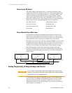
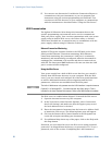
External Monitoring of Output Voltage and Current
The J1 connector also provides analog signals for monitoring the
output voltage and current. Selection of the voltage range between 0
– 5 V or 0 – 10 V is made by SW1 setup switch 4. The monitoring
signals represent 0 to 100% of the power supply output voltage and
current rating. The monitor outputs have a 500 Ω series output
resistance. Make sure that the sensing circuit has an input resistance
greater than 500 kΩ or the accuracy will be reduced.
SW1 switch 4 Voltage
range
J1 signal
connection
Signal function
Down (default) 0 – 5 V J1 pin 11 Voltage Monitor
J1 pin 24 Current Monitor
Up 0 – 10 V J1 pin 11 Voltage Monitor
J1 pin 24 Current Monitor
J1 pin 12 is the signal common for J1 pins 11 and 24.
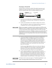
1
14
13
25
10 9
23
22
CURRENT LIMIT
PROGRAMMING
OUTPUT VOLTAGE
PROGRAMMING
PROGRAMMING
RESISTOR
PROGRAMMING
RESISTOR
OPTIONAL SETS
LOWER LIMIT
OPTIONAL SETS
LOWER LIMIT
OPTIONAL SETS
UPPER LIMIT
OPTIONAL SETS
UPPER LIMIT
12 8