


Installation 2
Series N5700 User’s Guide 25
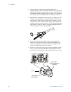
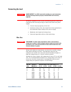
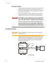
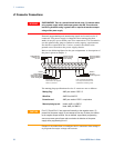
The J2 connector plug specifications are as follows:
Plug Type:
MC 1.5/5-ST-3.81, Phoenix
Wire Size:
AWG 28 to AWG 16
Stripping Length:
7 mm (0.28 in.)
Torque:
0.22 – 0.25 Nm (1.95 – 2.21 in-lb.)
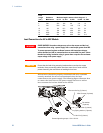
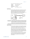
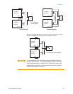
Local Sensing
The power supply is shipped with the rear panel J2 sense connector
wired for local sensing of the output voltage. With local sensing, the
output voltage regulation is made at the output terminals. This
method does not compensate for voltage drop on the load wires,
therefore it is recommended only for low load current applications or
where the load regulation is less critical. The following figure
illustrates the internal connections of the J2 connector.
NOTE
If the power supply is operated without the local sense jumpers or without the
remote sense lines connected, it will continue to work, but the output voltage
regulation will be degraded. Also, the OVP circuit may activate and shut down
the power supply. Note that the internal wiring between +V and + local sense
and between –V and – local sense will fail if load current flows through it.
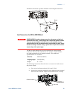
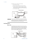
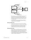
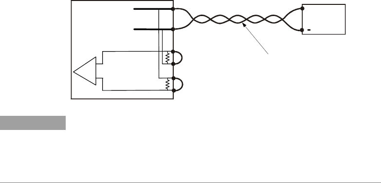
Remote Sensing
Use remote sensing in applications where load regulation at the load
is critical. Remote sensing allows the power supply to automatically
compensate for the voltage drop in the load leads. Refer to Appendix
A for the maximum allowable voltage drop on the load wires.
Remote sensing is especially useful in constant voltage mode with
load impedances that vary or have significant lead resistance. It has
no effect in constant current mode. Because sensing is independent
of other power supply functions it can be used regardless of how the
power supply is programmed. With remote sensing, voltage readback
monitors the load voltage at the remote sense points.
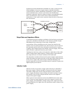
Use twisted or shielded wires to minimize noise pick-up. If shielded
wires are used, the shield should be connected to the ground at one
point, either at the power supply chassis or the load ground. The
optimal point for the shield ground should be determined by
experimentation.
-
-
Rem.sense
Local sense
Local sense
Rem.sense
+
Load lines, twisted
pair, shortest length
possible.
+V
-V
Load
+
Power
Supply
+
Error
Amp.