


Removing and Installing a PRP
24
Performance Route Processor Installation and Configuration Guide
OL-11656-01
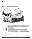
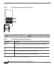
Step 6 Place your thumbs on the ends of each of the ejector levers and simultaneously
pull them both away from the PRP faceplate (in the direction shown in Figure 6a)
to release the PRP from the upper card cage slot and to dislodge the PRP edge
connector from the backplane.
Step 7 Grasp the PRP faceplate handle with one hand and pull the PRP straight out of the
slot, keeping your other hand under the PRP to guide it. Keep the PRP edge
connector parallel to the backplane.
Caution Avoid touching the PRP printed circuit board, components, or any edge connector
pins.
Step 8 Place the removed PRP on an antistatic mat or foam. If you plan to return the PRP
to the factory, immediately place it in an antistatic bag to prevent ESD damage.
Installing a PRP
When you install a PRP, be sure to use the ejector levers, which help to ensure that
the PRP is fully inserted in the backplane connector. (See Figure 6.) When you
push the ejector levers simultaneously inward (toward the center of the PRP), the
ejector levers push the PRP into the slot and ensure that the PRP backplane
connector is fully seated in the backplane.
Caution A PRP that is only partially connected to the backplane can halt the system.
To install a PRP, follow these steps:
Step 1 Turn off system power.
Step 2 Attach an ESD-preventive wrist strap and follow its instructions for use.
Step 3 Grasp the PRP faceplate handle with one hand and place your other hand under
the carrier to support and guide it into an upper card cage slot.