


31
Performance Route Processor Installation and Configuration Guide
OL-11656-01
Checking the Installation
The interface-specific LEDs on line cards might not go on until after you
configure the line card interfaces. To verify correct operation of each interface,
complete the first-time setup procedures and configuration, then refer to the LED
descriptions in the configuration notes for each line card to check the status of the
interfaces.
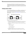
Verifying Interface Status
The status LEDs on the PRP indicate system and PRP status, which Flash disk slot
is active, which Ethernet connection is in use, and what is occurring on the
Ethernet interface. This section provides functional descriptions of the status
LEDs on the PRP-1 and PRP-2 (see Figure 8 and Figure 9) and the processes you
should observe.
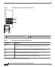
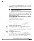
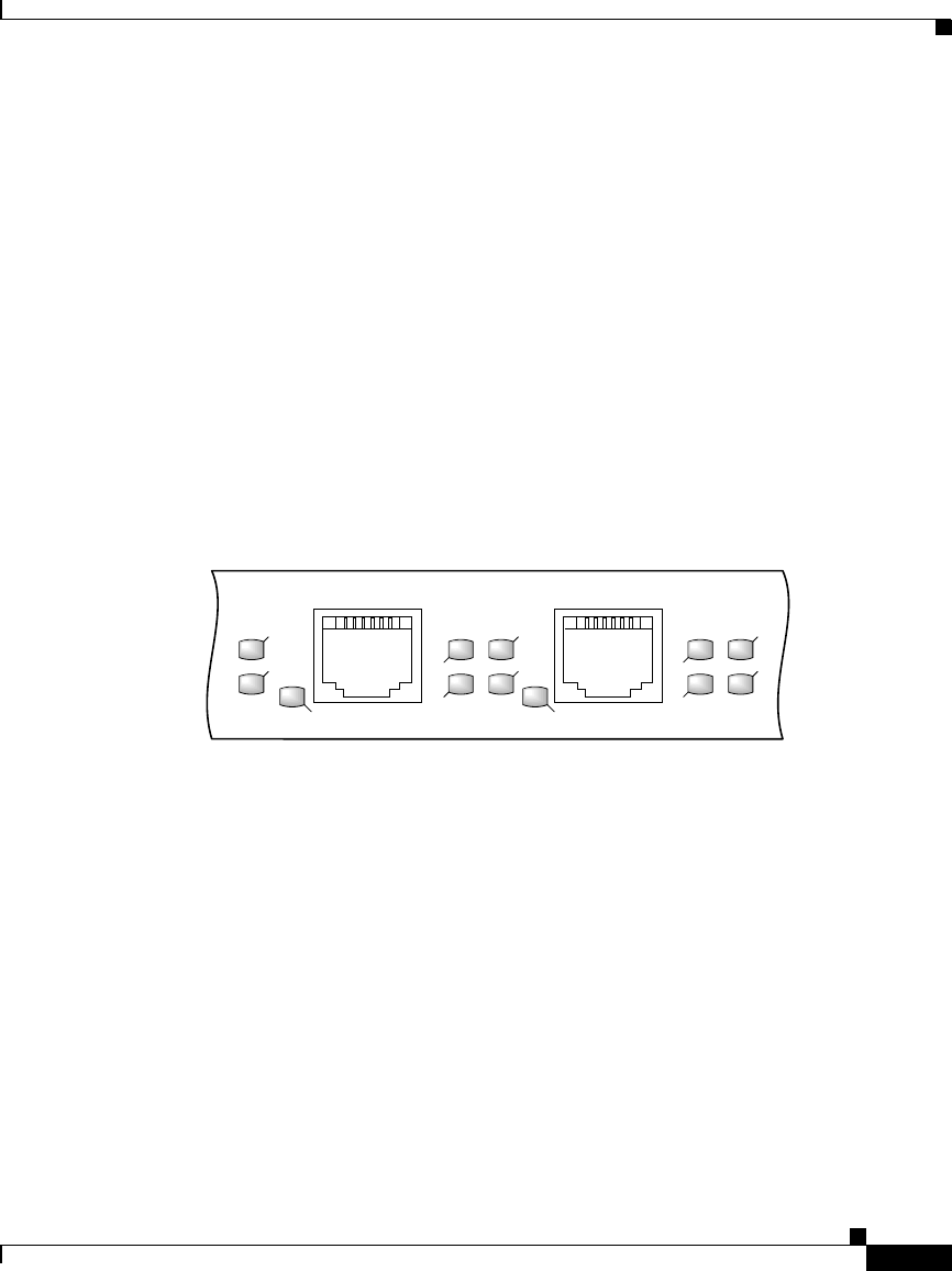
Figure 8 PRP-1 LEDs (Partial Front Panel View)
The PRP-1 has the following LED indicators:
• Two Flash disk activity LEDs, one for each Flash disk slot (labeled SLOT-0
and SLOT-1)—Identify which of the two Flash disk slots is accessed.
• Four Ethernet port LEDs used in conjunction with each of the RJ-45 Ethernet
connectors:
–
LINK—link activity
–
EN—port enabled
–
TX—data transmission
–
RX—data reception
• Two Ethernet connection LEDs, one for each Ethernet port (labeled
PRIMARY)—Identify which of the two Ethernet connections is selected.
RX
TX
PRIMARY
SLOT-1
SLOT-0
LINK
EN
RX
TX
ETH 1ETH 0
LINK
PRIMARY
EN
70693