


Configuring Interfaces on the PRP
48
Performance Route Processor Installation and Configuration Guide
OL-11656-01
Ethernet Interface Cable Connection Procedure
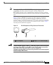
The RJ-45 receptacles on the PRP-1 provide two physical connection options for
Ethernet interfaces and three physical connections on the PRP-2. RJ-45 cables are
not available from Cisco Systems; they are available from commercial cable
vendors. To connect cables to the PRP Ethernet interfaces (ports labeled ETH0,
ETH1 and ETH2; see Figure 8 and Figure 9), attach the Category 5 UTP cable
directly to an RJ-45 receptacle on the PRP.
The Ethernet interfaces on the PRP are end-station devices, not repeaters;
therefore, you must connect an Ethernet interface to a repeater or hub.
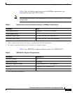
Note Only connect cables that comply with EIA/TIA-568 standards. (See Table 4 and
Table 5 for cable recommendations and specifications.)
Note To comply with Telcordia GR-1089 NEBS standard for electromagnetic
compatibility and safety, connect all console, auxiliary, Ethernet, and
BITS (PRP2) interfaces only to intrabuilding or nonexposed wiring or cabling.
The intrabuilding cable must be shielded and the shield must be grounded at both
ends.
Caution The Ethernet ports are used primarily as Telnet ports into the Cisco 12000 Series
Router, and for booting or accessing Cisco IOS software images over a network
to which an Ethernet port is directly connected. Cisco Express Forwarding (CEF)
functions are switched off by default for security reasons. Cisco strongly cautions
you to consider the security implications of switching on CEF routing functions
on these ports.
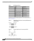
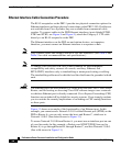
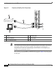
Figure 13 shows an example of the functionality of an Ethernet port. In this
example, you cannot access Network 2.0.0.0 via the Ethernet port (ETH0) on the
PRP in Router A; you can only access the hosts and Router C, which are in
Network 1.0.0.0. (See dotted arrows in Figure 13.)
To access Network 2.0.0.0 from Router A, you must use an interface port on one
of your line cards (in this example, a Packet-over-SONET [POS] line card in
Router A) to go through Router B, through Router C, and into Network 2.0.0.0.
(See solid arrows in Figure 13.)