


53
Performance Route Processor Installation and Configuration Guide
OL-11656-01
Configuring Interfaces on the PRP
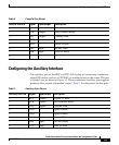
Configuring the Auxiliary Interface
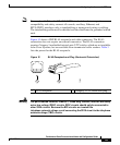
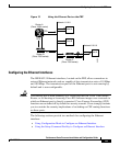
The auxiliary port on the PRP is a DTE, RJ-45 plug for connecting a modem or
other DCE device (such as a CSU/DSU or another router) to the router. The port
is labeled Aux, as shown in Figure 14. The asynchronous auxiliary port supports
hardware flow control and modem control. Table 7 lists the pinout for this port.
Table 6 Console Port Pinout
Console Port Pin Signal Input/Output Description
1
1
1. These pins are connected to each other.
—— —
2 DTR Output Data Terminal Ready
3 TxD Output Transmit Data
4 GND — Signal Ground
5 GND — Signal Ground
6 RxD Input Receive Data
7 DSR Input Data Set Ready
8
1
—— —
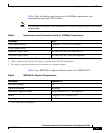
Table 7 Auxiliary Port Pinout
Auxiliary Port Pin Signal Input/Output Description
1 RTS Output Request To Send
2 DTR Output Data Terminal Ready
3 TxD Output Transmit Data
4 GND — Signal Ground
5 GND — Signal Ground
6 RxD Input Receive Data
7 DSR Input Data Set Ready
8CTSInputClear To Send