


25
Performance Route Processor Installation and Configuration Guide
OL-11656-01
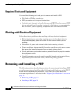
Removing and Installing a PRP
Caution Avoid touching the PRP printed circuit board, components, or any edge connector
pins.
Step 4 Place the bus-connector edge of the PRP in the appropriate slot and align the
notches along the edge of the carrier with the grooves at the top and bottom of the
slot.
Step 5 While keeping the PRP edge connector parallel to the backplane, carefully slide
the carrier into the slot until the PRP faceplate makes contact with the ejector
levers, then stop.
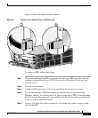
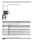
Step 6 Using the thumb and forefinger of each hand to pinch each ejector lever, push both
ejectors simultaneously toward the center of the PRP faceplate until they are
perpendicular to the PRP faceplate. (See Figure 6b.)
Step 7 Using a 3/16-inch flat-blade screwdriver, tighten the captive screws on the ends
of the PRP. The captive screws prevent the PRP from becoming partially
dislodged from the backplane and ensure proper EMI shielding. (These captive
screws must be tightened to meet EMI specifications.)
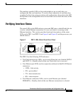
Step 8 If you disconnected cables to remove the PRP, or if you are installing a new PRP,
reconnect the cables to the appropriate ports. (See the “Checking the Installation”
section on page 26.)
Step 9 Ensure that the console terminal is turned on.
Step 10 Turn on system power.
Step 11 Attach the network end of your RJ-45 cable to your transceiver, switch, hub,
repeater, DTE, or other external equipment. Be sure to use the appropriate strain
relief on cable connections.