


Additional Configuration and Maintenance Tasks
78
Performance Route Processor Installation and Configuration Guide
OL-11656-01
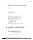
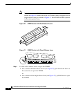
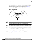
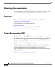
Step 5 To position the DIMM for insertion, orient it at the same angle as the DIMM
socket. The two notches (keys) on the bottom edge of the module ensure that the
DIMM edge connector is registered properly in the socket. (See Figure 22.)
If necessary, rock the DIMM back and forth gently to align it in the socket.
Figure 22 Handling a DIMM
Caution When inserting DIMMs into a socket, apply firm, but not excessive, pressure. If
you damage a DIMM socket, you must return the line card for repair.
Step 6 Gently insert the DIMM into the socket and push until the DIMM snaps into place
and the release lever is flush against the side of the socket.
Step 7 Verify that the release lever is flush against the side of the socket. If it is not, the
DIMM might not be seated properly. On a socket with dual release levers, both
levers should be flush against the sides of the DIMM.
If the module appears misaligned, carefully remove it and reseat it, ensuring that
the release lever is flush against the side of the DIMM socket.
Step 8 Repeat Step 3 through Step 7 to install any remaining DIMMs for your memory
configuration.
H6507
Key