


Configuring Interfaces on the PRP
46
Performance Route Processor Installation and Configuration Guide
OL-11656-01
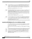
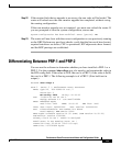
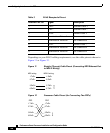
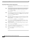
Depending on your RJ-45 cabling requirements, use the cable pinouts shown in
Figure 11 or Figure 12.
Figure 11 Straight-Through Cable Pinout (Connecting MDI Ethernet Port
to MDI-X Wiring)
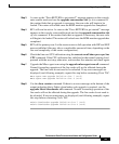
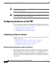
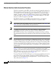
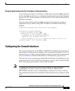
Figure 12 Crossover Cable Pinout (for Connecting Two PRPs)
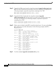
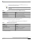
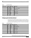
Table 3 RJ-45 Receptacle Pinout
Ethernet Port Pin Signal Description
1 TxD+ Transmit data +
2 TxD– Transmit data –
3 RxD+ Receive data +
4 Termination Network No connection
5 Termination Network No connection
6 RxD– Receive data –
7 Termination Network No connection
8 Termination Network No connection
MDI-X wiringMDI wiring
1 TxD+
2 TxD–
3 RxD+
6 RxD–
1 RxD+
2 RxD–
3 TxD+
6 TxD–
H11007
PRP
1 TxD+
2 TxD–
3 RxD+
6 RxD–
1 TxD+
2 TxD–
3 RxD+
6 RxD–
75431
PRP