


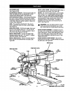
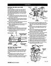
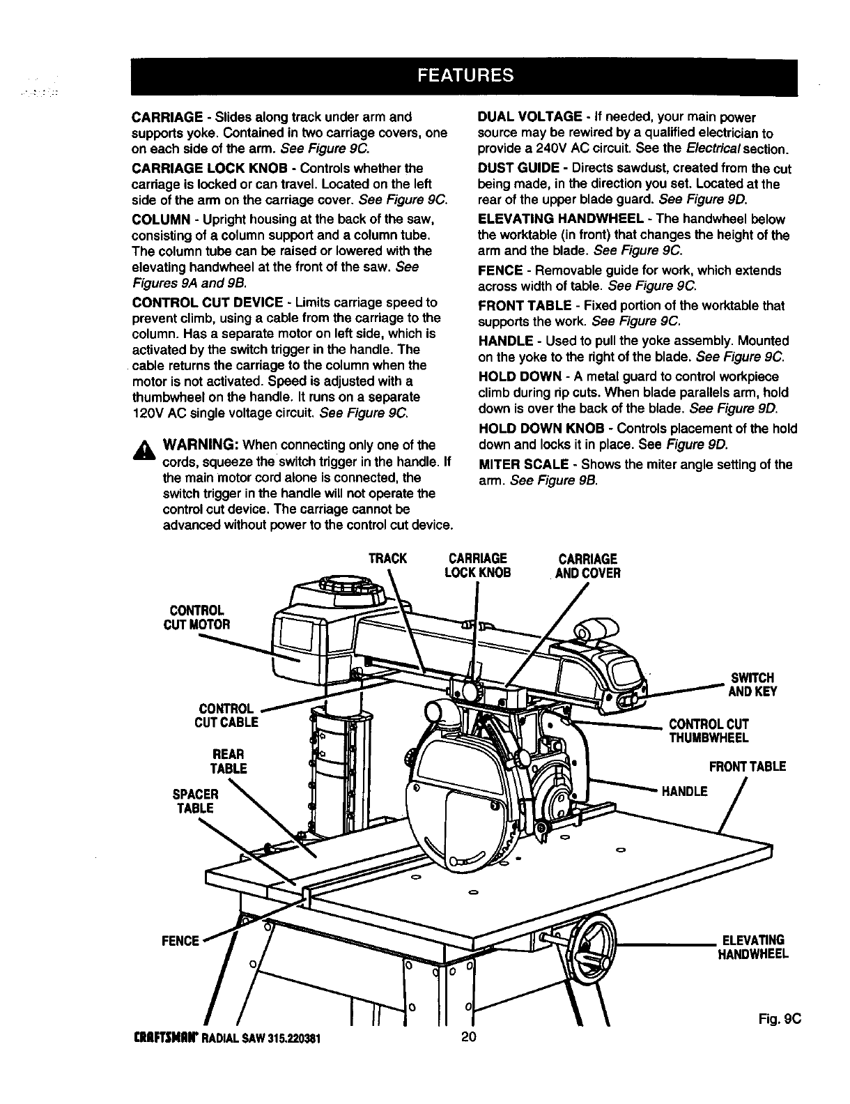
CARRIAGE-Slidesalongtrackunderarmand
supportsyoke.Containedintwocarriagecovers,one
oneachsideofthearm.See Figure9C.
CARRIAGE LOCK KNOB - Controlswhether the
cardage islocked or can travel. Locatedon the left
side ofthe arm onthe carriage cover. See Figure 9C.
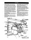
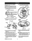
COLUMN - Upright housingat the beck ofthe saw,
consistingofa column supportand a columntube.
The column tube can be raisedor lowered withthe
elevating handwheel at the front ofthe saw. See
Figures 9A and 9B.
CONTROL CUT DEVICE - Limitscarriage speed to
preventclimb, usinga cable from thecarriage to the
column. Has a separate motor on left side, which is
activated by the switchtrigger inthe handle. The
cable returnsthe carriage tothe columnwhen the
motoris not activated. Speed is adjusted with a
thumbwheelon the handle. It runson a separate
120V AC single voltage circuit.See Figure 9C.
_1, WARNING: When connectingonlyone ofthe
cords, squeeze the switchtrigger inthe handle.If
the main motorcord alone isconnected,the
switchtrigger inthe handle will notoperate the
controlout device. The carriage cannot be
advancedwithout powertothe controlcutdevice.
DUAL VOLTAGE - If needed, your main power
sourcemay be rewired by a qualified electricianto
providea 240V AC circuit.See the Electricalsection.
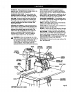
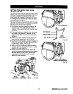
DUST GUIDE - Directssawdust, created from the cut
being made, in the directionyou set. Locatedat the
rear ofthe upper blade guard. See Figure 9D.
ELEVATING HANDWI-IEEL - The handwbeel below
the worktable (in front) thatchanges the heightofthe
arm and the blade. See Figure9C.
FENCE - Removable guide for work, whichextends
acrosswidthof table. See Figure 9C.
FRONT TABLE - Fixed portionofthe worktable that
supportsthe work. See Figure 9C.
HANDLE - Used to pullthe yoke assembly. Mounted
on the yoke to the rightofthe blade. See Figure 9C.
HOLD DOWN - A metal guard tocontrolworkpiece
climbduring rip cuts.When blade parallelsarm, hold
down isover the backof the blade. See Figure 9D.
HOLD DOWN KNOB - Controls placement ofthe hold
down and locks it in place. See Figure 9D.
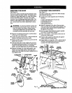
MITER SCALE - Shows the miter angle settingofthe
arm. See Figure 9B.
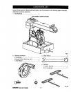
TRACK CARR_GE CARRIAGE
LOCKKNOB ANDCOVER
CONTROL
CUTMOTOR
CUTCABLE
REAR
TABLE
SPACER
TABLE
SWITCH
ANDKEY
CONTROLCUT
THUMBWHEEL
FRONTTABLE
ELEVATING
HANDWHEEL
Fig. 9C
[RFT|NnlrRADIALSAW315.220381 20