


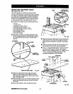
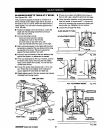
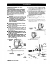

PARALLELING BLADE TO TABLE
See Figures 32A-32C.
This procedure squares the blade to the table at 90"
bevel so horizontalcutswill be accurate. This also
reduces kickback,as well as splinteringand burning
of the cut edges of the workpiece. If the blade is not at
90" bevel, follow the stepsto rotate the blade unit
slightly.You willneed a framing square and a flat
blade screwdriver.
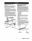
_k WARNING: The blade mustbe perfectlyparallel
to thetable at the 90" reading on the bevel scale,
If not, kickbackcould result,as well as splinter-
ingor burningthe cut. Kickbackcan resultin
serious personal injuryas the workpiece can be
thrown at the operator.
• Use the arm lock knobto lock thearm in 0° miter
position(straightforward).
• Turn the elevating handwheel to raisethe bladeat
least 2 in.above the table.
Release the bevel lock lever belowthe handle. Use
the bevel indexknob, just under the handle, toturn
the motorto 90". The blade willbe horizontal. Lock
the bevel lock lever.
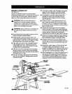
• Placethe framing square withthe shortend hang-
ingdownin frontofthe worktableand the longside
on edge underthe blade.
• Lowerthe arm withthe elevating handwheelsothe
bladesurface restson the square. Turn the blade
slightlyifnecessary sothe face ofthe blade, nota
tooth, lieson the square.
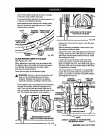
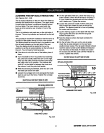
NOADJUSTMENT
NEEDED
FENCE
BEVEL
LEVER
BLADE
FRONTTABLE
FRAMING
SOUARE
Fig. 32A
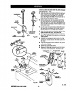
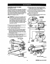
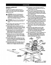
• Check whetherthe blade isfiat againstthe edge
the entirelengthor whether a gap is visible.Ifyou
can see a gap, adjustthe bladeto be at 90" bevel
tothe table with the followingsteps.
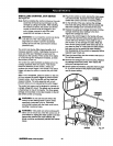
• Unlockthe bevel locklever. Loosenthe rearmotor
mountnut,whichholdsthe motoron the yoke,
Placea flatblade scrawddver inone of the slots,
and rotatethe cam behind the nutto eliminatethe
gap betweenthe bladeand the square.
• Retightenthe nut.
• Tightenthe bevel lock lever. Recheck the blade
and the square forany gaps.
• Raise the bladewith the elevating handwheelto
approximatelyhalfwayup. Index the bladeto a
vertical0° bevel with the bevel index knob. Lockit
with the bevel locklever.
ADJUSTMENT GAP
NEEDED
:=A--
GAP
Fig. 32B
CAM'
Fig. 32C
[RIIFrSMIIIr RADIALSAW315.220381 40