


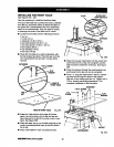

INSTALLING THE FRONTTABLE
See Figures 23A - 23C.
Use this procedure to installthe fixed fronttable.
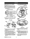
The top ofthe table has counterbored holes, predrilled
from the top, around the center to attach the table. In
the center are acounterbored hole and a small hole,
which isnot counterbored.They are used for raising
or lowering the center ofthe table until itis level.
• Locate thefronttable and the followinghardware:
1 tee nut
1 U-clip (1/4 in.)
1 setscrew (1/4-20 x 7/8 in.)
4 pan head screws (1/4-20 x 1 in.)
1 pan head screw (1/4-20 x 1-3/4 in.)
5 flat washers (5/8 in.)
4 lock washers (1/4 in.)
4 hex nuts(1/4-20)
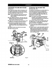
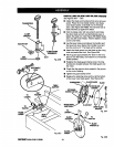
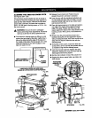
• Place thefronttable on a solidworksurface,with
the top surface face down. Race thetee nut inthe
non-counterboredhole and tap it in place witha
hammer.
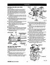
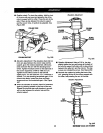
U-CLIP AUGNU-CUP
OVERTHISHOLE
SAWBASE
Fig. 23B
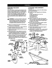
• Place the long pan head screw intothe center hole
and thread intothe U-clip. Do nottighten untilthe
SETSCREW table has beenchecked for evenness. See Figure
_ SCREW 23A.
f_l _'_._,_ FLAT • Place thesetscrewthroughthe small levelinghole
r I _ WASHER and thread intothe tee nut, butdo not tighten.
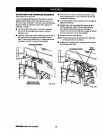
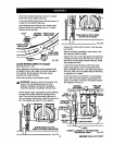
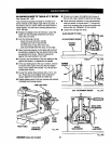
ol ___ _k • Puta 1 in. long pan head screwin the four remain-
ingholesand throughthe holes inthe support.
Cap with a lock washer and hex nut.Tightenwith a
7/16 in.wrench and phillipsscrewdriver. This
REAROF completes installationofthe fronttable.
1-3/4in.SCREW/|
SCREW L !'I / ELAT
] _' T' ' WASHER
- i
REAROFFRONTTABLE Fig. 23A
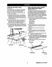
• Snap the U-clip ontothe frontedge of the saw
base. Line up the hole inthe U-clip withthe saw
base holejustto the left ofthe center notchin saw
base. See Figure23B.
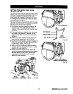
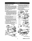
• Place thetable, top up, on the table supportssothe
center counterboredhole linesup over the hole in
the U-clip.
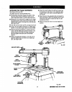
• Place a flat washer in each counterborsdhole.
LOCKWASHER
HEXNUT
Fig. 23C
[|lll_NlUr RADIALSAW315.220381 32