


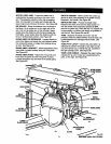
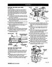
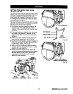
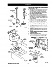
SETTING THE BEVEL LOCK LEVER
See Figures 18A-18C.
The bevel lock lever locksthe blade at desired angles
otherthan the presetpositive stop angles. The bevel
lock lever is preset at the factory but may need
readjustment after shippingor extended use. Check
for overUghtnessor looseness and make any neces-
sary adjustments as follows:
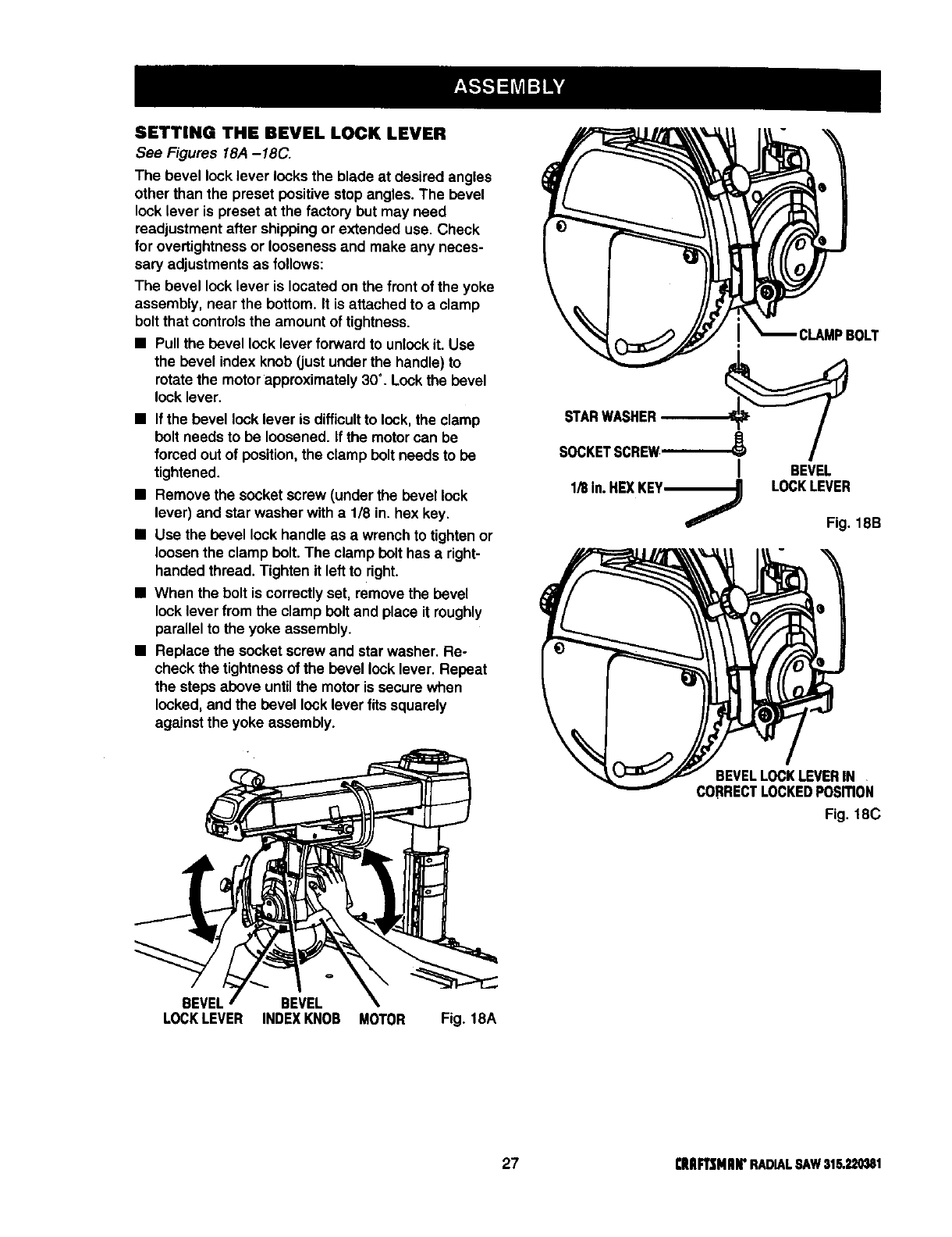
The bevel lock lever is locatedon the front ofthe yoke
assembly, near the bottom.It isattached to a clamp
boltthat controlsthe amount oftightness.
• Pullthe bevel lock lever forward to unlockit. Use
the bevel indexknob (justunder the handle) to
rotate the motorapproximately30°. Lock the bevel
lock lever.
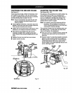
• Ifthe bevellock lever is difficultto lock,the clamp
boltneeds to be loosened. If the motorcan be
forced out of position, the clamp belt needs tobe
tightened.
• Remove the socketscrew (under the bevel lock
lever) and star washer with a 1/8 in. hex key.
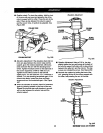
• Use the bevel lock handle as a wrenchtotighten or
loosenthe clampbelt. The clamp bolthas a right-
handed thread. Tighten itleftto right.
• When the bolt iscorrectlyset, remove the bevel
lock lever from the clamp boltand place it roughly
parallelto the yoke assembly.
• Replace the socketscrew and star washer. Re-
check thetightnessof the bevel locklever. Repeat
the steps above untilthe motorissecure when
locked, and the bevel lock lever fits squarely
againstthe yoke assembly.
STARWASHER
1/8In.HEXKEY------_
BEVEL
LOCKLEVER
Fig. 18B
BEVELLOCKLEVERIN
CORRECTLOCKEDPosmoN
Fig. 18C
BEVEL BEVEL
LOCKLEVER INDEXKNOB MOTOR Fig. 18A
27 [RIIFTSMIIIr RADIALSAW31S.22_1