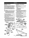
REMOVING THE BLADE
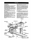
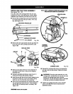
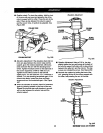
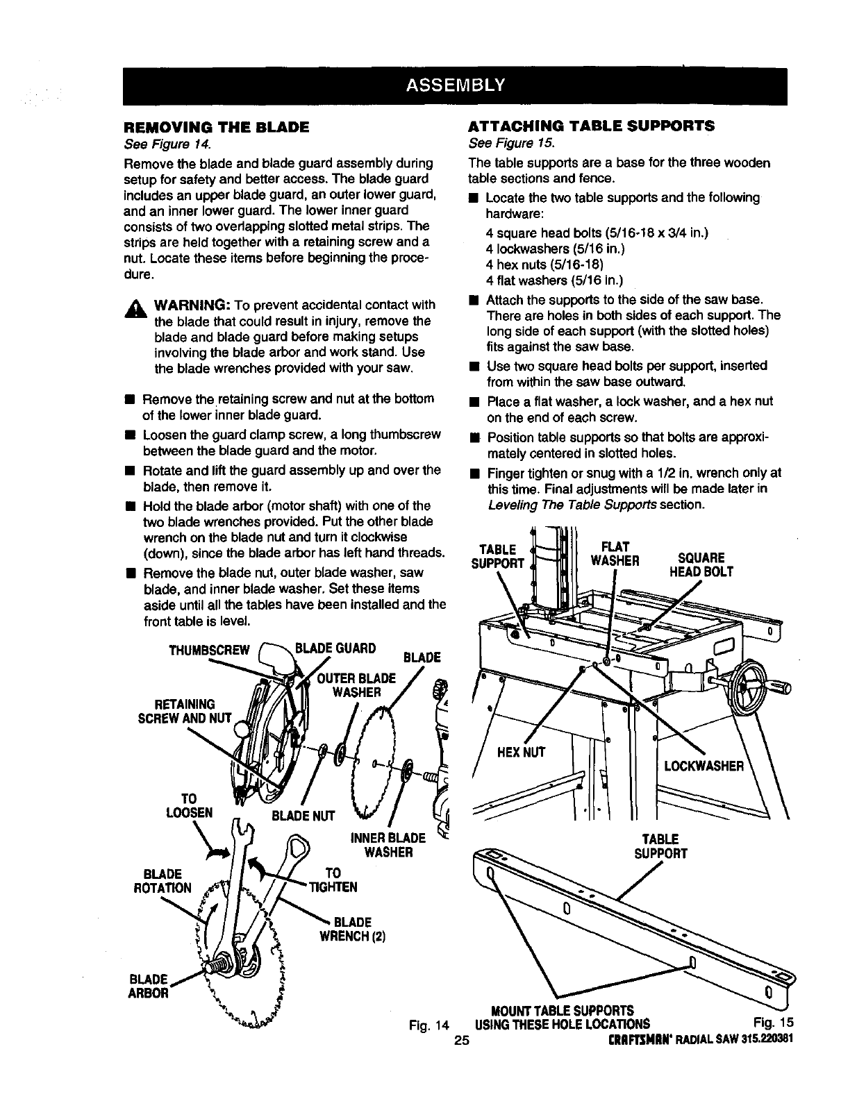
See Figure 14.
Remove the blade and blade guard assembly during
setup for safety and better access. The blade guard
includesan upper blade guard, an outer lowerguard,
and an innerlower guard.The lower inner guard
consistsoftwo overlappingslotted metalstrips. The
stripsare held together with a retaining screwand a
nut. Locate these itemsbefore beginningthe proce-
dure.
_, WARNING: To prevent accidental contactwith
the blade that could resultin injury, remove the
blade and blade guard before making setups
involvingthe blade arborand work stand. Use
the blade wrenches providedwith yoursaw.
• Remove the retainingscrewand nutat the bottom
of the lower innerblade guard.
• Loosenthe guard clamp screw,a longthumbscrew
between the bladeguard and the motor.
• Rotate and liftthe guard assembly up and over the
blade, then remove it,
• Hold the blade arbor (motorshaft)with one of the
two blade wrenches provided.Putthe other blade
wrench on the blade nut and turnitclockwise
(down), since the bladearbor hasleft handthreads.
• Remove the blade nut,outer blade washer, saw
blade, and inner bladewasher, Setthese items
aside untilall the tables have been installedand the
fronttable islevel.
THUMBSCREW
BLADEGUARD
BLADE
RETAINING
SCREWANDNUT
TO
LOOSEN
\
BLADE
ROTATION
TO
INNERBLADE
WASHER
ATTACHING TABLE SUPPORTS
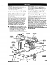
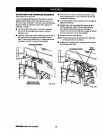
See Figure 15.
The table supportsare a base forthe threewooden
table sectionsand fence.
• Locatethe two table supportsand the following
hardware:
4 square head bolts(5/16o18x 3/4 in.)
4 Iockwashers(5/16 in.)
4 hexnuts (5/16-18)
4 flat washers (5/16 in.)
• Attachthe supportstothe sideof the saw base.
There are holesin both sidesof each support.The
longside ofeach support(withthe slottedholes)
fits againstthe saw base.
• Use two square head bolts per support,inserted
from withinthe saw base outward.
• Place a flat washer, a lock washer, and a hex nut
onthe end ofeach screw.
• Positiontable supportsso thatbolts are approxi-
mately(;enteredin slottedholes.
• Fingertightenor snugwith a 112in.wrenchonlyat
thistime. Final adjustmentswill be made later in
Leveling The Table Supports section.
TABLE
SUPPORT
FLAT
WASHER
SQUARE
HEADBOLT
TABLE
SUPPORT
BLADE
WRENCH(2)
BLADE
ARBOR
MOUNTTABLESUPPORTS
Fig, 14 USINGTHESEHOLELOCATIONS Fig. 15
25 rRBFTSMIIB°RADIALSAW315.220381


