


ALIGNING BLADE TO TABLE AT 0° BEVEL
See Figures 30A - 30D.
This procedure squaresthe blade tothe table at O"
bevel (vertical)so the blade angle willbe accurate. If
the blade is r_otat O"bevel, follow the stepsbelow to
rotate slightly.You willneed a framing square and a
1/4 in. hex key.
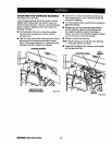
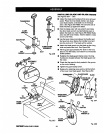
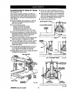
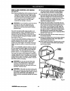
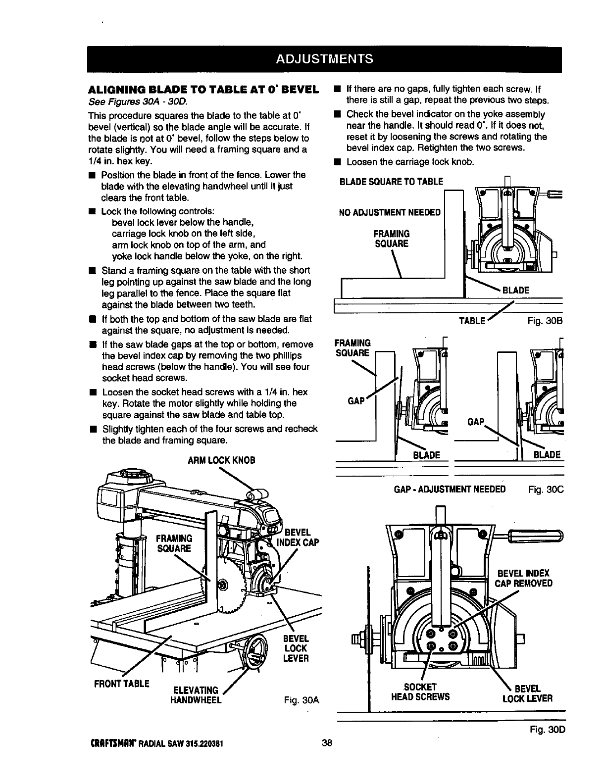
• Positionthe blade in frontofthe fence. Lowerthe
blade withthe elevating handwheel untilitjust
clears the fronttable.
• Lockthe followingcontrols:
bevel lock lever below the handle,
carriage lock knobon the leftside,
arm lock knobon top ofthe arm, and
yoke lockhandle below the yoke, on the right.
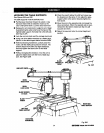
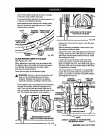
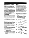
• Stand a framing square on the table with the short
leg pointingup againstthe saw blade and the long
leg parallelto thefence. Placethe squareflat
against the blade between two teeth.
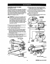
• If boththe top and bottomofthe saw blade aN flat
against the square, no adjustment isneeded.
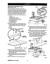
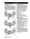
• Ifthe sawblade gaps at thetop or bottom, remove
the bevel indexcap by removingthe two phillips
head screws(belowthe handle). You willsee four
sockethead screws.
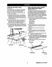
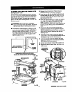
• Loosenthe sockethead screwswith a 1/4 in. hex
key. Rotate the motorslightlywhile holdingthe
square againstthe saw blade and table top.
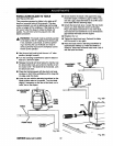
• Slightlytighten each ofthe four screwsand recheck
the blade and framing square.
ARMLOCKKNOB
• Ifthere are no gaps, fully tighten each screw. If
then isstilla gap, repeat the previoustwosteps.
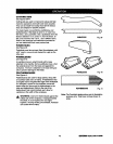
• Check the bevel indicatoronthe yokeassembly
near the handle. It shouldread 0% Ifitdoes not,
reset itby looseningthe screws and rotatingthe
bevel indexcap. Retightenthe two screws.
• Loosenthe carriage lock knob.
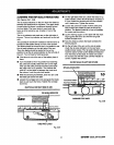
BLADESQUARETOTABLE
NOADJUSTMENTNEEDED
FRAMING
SQUARE
FRAMING
SQUARE
BLADE
TABLE/ Fig. 3OB
GAP
BLADE
FRONTTABLE
INDEXCAP
BEVEL
LOCK
LEVER
ELEVATING
HANDWHEEL Fig. 3OA
GAP-ADJUSTMENTNEEDED
m
41 ¸
41
SOCKET
HEADSCREWS
Fig. 3OC
BEVELINDEX
CAPREMOVED
_ BEVEL
LOCKLEVER
Fig. 30D
ClIIIFTSMJlrRADIALSAW315.220381 38