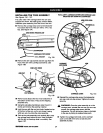
INSTALLING THE YOKE ASSEMBLY
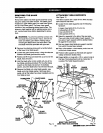
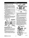
See Figures 13A - 13C.
The yoke rides in the carriage below the arm and
supports the motor, the blade guard, and the blade.
Install the yoke assembly from the front of the arm.
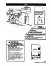
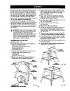
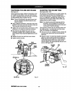
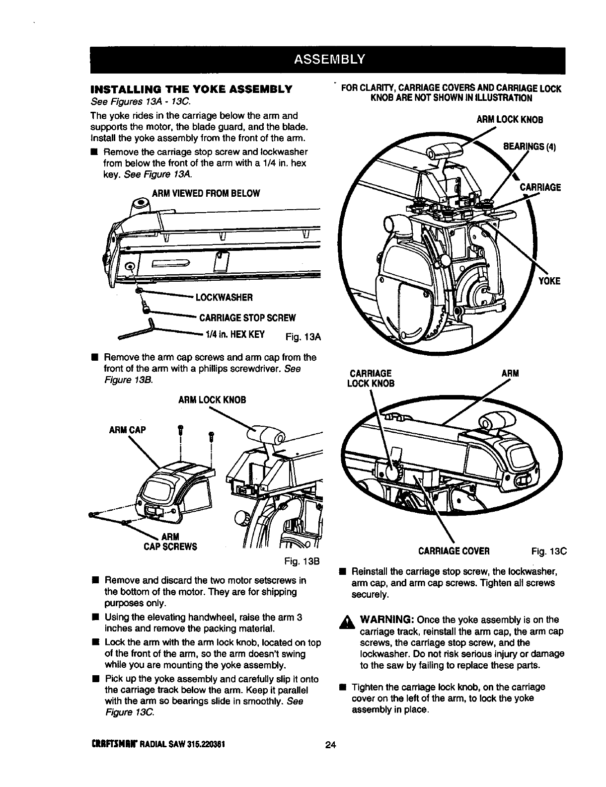
• Remove the carriage stop screw and Iockwasher
from below the front of the arm with a 1/4 in. hex
key. See Figure 13A.
ARMVIEWEDFROMBELOW
='_"____._LcOC KWASHER
sc.°w
q::==::::===_l,_ , Fig. 13A
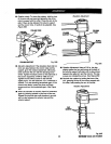
• Remove the arm cap screwsand arm capfrom the
frontofthe arm witha phillipsscrewdriver. See
Figure 13B.
ARMLOCKKNOB
ARM
CAPSCREWS
Fig. 13B
• Remove and discard the two motorsetscrews in
the bottomofthe motor.They are for shipping
purposesonly.
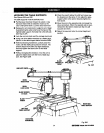
• Using the elevating handwheel, raisethe arm 3
inchesand remove the packingmaterial.
• Lock the arm withthe arm lockknob, located ontop
ofthe front ofthe arm, sothe arm doesn'tswing
whileyou are mountingthe yoke assembly.
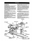
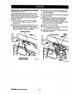
• Pickup the yoke assembly and carefullyslipitonto
the carriage track below the arm. Keep it parallel
with the arm so bearings slide insmoothly.See
Figure 13C.
• FORCLARITY,CARRIAGECOVERSANDCARRIAGELOCK
KNOBARENOTSHOWNINILLUSTRATION
ARMLOCKKNOB
BEARINGS(4)
CARRIAGE
YOKE
CARRIAGE ARM
LOCKKNOB
CARRIAGECOVER Fig. 13C
• Reinstallthe cardage stop screw,the Iockwasher,
arm cap, and arm cap screws.Tightenall screws
securely.
_1, WARNING: Once the yoke assembly ison the
carriage track, reinstallthe arm cap, the arm cap
screws, the cardage stopscrew, and the
Iockwasher. Do not dsk sedousinjuryor damage
tothe saw byfailing to replacethese parts.
• Tighten the carriage lockknob, on the carriage
cover on the leftofthe arm, to lockthe yoke
assembly in place.
CIUIFt3MlUf RADIALSAW315.220381 24


