


Chapter 5 Parameters|VFD-S Series
Revision August 2006, SE08, SW V2.61 5-63
9-03 Time-out Detection
Factory Setting: d0
Settings d0 Disable
d1 1 sec
d2 2 sec
:
d20 20 sec
If this function is enabled, the timer will start counting once the first valid Modbus
communication signal is received after power-up or reset. The timer will reset to 0 after each
valid Modbus communication message is received. If the watchdog timer reaches the value
set in Pr. 9-03, the drive will stop its output and display the message "CE10" on the digital
keypad. This fault can reset by an external terminal, keypad or a Modbus communication
reset command.
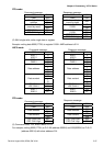
9-04 Communication Protocol
Factory Setting: d0
Settings d0 Modbus ASCII mode, protocol <7,N,2>
d1 Modbus ASCII mode, protocol <7,E,1>
d2 Modbus ASCII mode, protocol <7,O,1>
d3 Modbus ASCII mode, protocol <8,N,2>
d4 Modbus ASCII mode, protocol <8,E,1>
d5 Modbus ASCII mode, protocol <8,O,1>
d6 Modbus RTU mode, protocol <8,N,2>
d7 Modbus RTU mode, protocol <8,E,1>
d8 Modbus RTU mode, protocol <8,O,1>
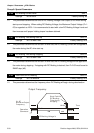
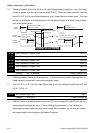
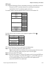
1. Computer Control
6
1
1: +EV
2: GND
3: SG-
4: SG+
There is a built-in RS-485 serial interface, marked (RJ-11 Jack) on the control terminal
block, for VFD-S Series. The pins are defined above. Each VFD-S AC drive has a pre-
assigned communication address specified by Pr. 9-00. The computer then controls
each AC drive according to its communication address.
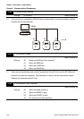
VFD-S can be setup to communicate on Modbus networks using one of the following
modes: ASCII (American Standard Code for Information Interchange) or RTU (Remote