


Chapter 5 Parameters|VFD-S Series
5-28 Revision August 2006, SE08, SW V2.61
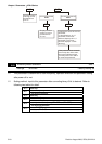
2-01 Source of Operation Command
Factory Setting: d0
Settings d0 Controlled by the keypad
d1 External terminals. Keypad STOP/RESET enabled.
d2 External terminals. Keypad STOP/RESET disabled.
d3 RS-485 serial communication (RJ-11). Keypad STOP/RESET
enabled.
d4 RS-485 serial communication (RJ-11). Keypad STOP/RESET
disabled.
When the AC drive is controlled by an external source, please refer to parameter group 4 for
detailed explanations on related parameter settings.
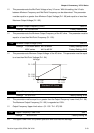
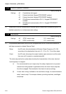
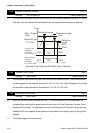
2-02 Stop Method
Factory Setting: d0
Settings d0 STOP: ramp to stop E.F.: coast to stop
d1 STOP: coast to stop E.F.: coast to stop
The parameter determines how the motor is stopped when the AC motor drive receives a
valid stop command or detects External Fault.
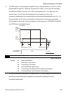
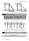
Ramp: the AC motor drive decelerates to Minimum Output Frequency (Pr.1-05)
according to the deceleration time set in Pr.1-10 or Pr.1-12 and then stops.
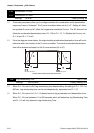
Coast: the AC motor drive stops the output instantly upon command, and the motor
free runs until it comes to a complete standstill.
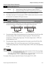
The motor stop method is usually determined by the characteristics of the motor load and
how frequently it is stopped.
(1) It is recommended to use “ramp to stop” for safety of personnel or to prevent
material from being wasted in applications where the motor has to stop after
the drive is stopped. The deceleration time has to be set accordingly.
(2) If motor free running is allowed or the load inertia is large, it is recommended to
select “coast to stop”. For example: blowers, punching machines, centrifuges
and pumps.