


Revision August 2006, SE08, SW V2.61 4-1
Chapter 4 Digital Keypad Operation
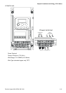
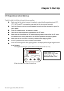
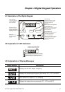
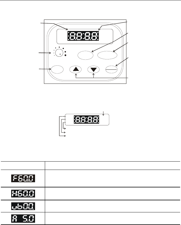
4.1 Description of the Digital Keypad
RUN
FWD
REV
STOP
MIN. MAX.
RUN
STOP/RESET
MODE
PROG
DATA
LED indication
Light during RUN,
STOP, FWD and
REV operation.
Potentiometer for
frequency setting.
Could be the Master
Frequency input
by setting Pr.2-00.
Mode Key
Change between
different display
modes.
LED Display
Indicate frequency, motor
parameter setting value
and alarm contents.
RUN Key
Start inverter drive operation.
STOP/RESET Key
Stop inverter drive operation
and reset the inverter after
faults occurred.
PROG/DATA Key
Set the different parameters
and enter information.
UP and DOWN Key
Sets the parameter number
or changes the numerical
data such as the freq.
reference.
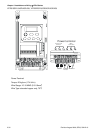
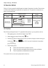
4.2 Explanation of LED Indicators
RUN
FWD
REV
STOP
Stop AC drive when STOP
button has been pressed.
RUN LED lights during RUN operation.
FWD LED lights during forward operation.
REV LED lights during reverse operation.
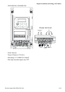
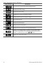
4.3 Explanations of Display Messages
Display Message Descriptions
Displays the AC drive Master Frequency.
Displays the actual output frequency at terminals U/T1, V/T2, and W/T3.
User defined unit (where U = F x Pr.00.05)
Displays the output current at terminals U/T1, V/T2, and W/T3.